Graph Modules List
This chapter includes descriptions of all available graph modules in the IndyEye app. It is also possible to find module-specific information in the app by clicking on the question mark icon after selecting a module. You can also quickly find out the details of any module by using the web page search function.
Sensor

- Camera : Acquire image from the camera. When multiple cameras and robots are used, set calibration file for each camera.
- For each camera, select a calibration file. NotReady is displayed for non-calibrated cameras.
Refinement

- Binarization : 이미지를 흑백으로 이진화 합니다.
- METHOD : The Method for the binarization.
- otsu : Automatically selects the best threshold. THRESHOLD is ignored.
- binary : Changes pixels over the threshold to white and below threshold to black.
- binary_inv : Changes pixels over the threshold to black and below threshold to white.
- trunc : Clips the pixel values over the threshold.
- to_zero : Changes pixel values under the threshold to zero.
- to_zero_inv : Changes pixel values over the threshold to zero.
- THRESHOLD : threshold for the binarization.
- METHOD : The Method for the binarization.
- Crop : Crops the image to the region of interest defined by an ROI module. After using this module, the size of the image cannot be linked to the robot coordinate system since the size of the image has changed.
- ROI : Specifies the region of interest of the image. Most algorithms after this module will only operate within these bounds.
- CENTER X, CENTER Y : The position of the center of the region of interest
- SIZE W, SIZE H : The height and width size of the region of interest
- TOUCH : Move the area of interest by touching the screen
- ROIFromMask : Creates a region of interest from the current mask. As with the ROI module, most algorithms after this module will only operate within these bounds.
- Resize : Resizes the image size to the (WIDTH, HEIGHT) specified. After using this module, the size of the image cannot be linked to the robot coordinate system since the size of the image has changed.
- Sharpen : Sharpen the image.
- GAMMA : The amount of sharpening (0 is the original image, the closer to 1 the more sharpening is done).
- SIGMA : The extent to which each pixel is affected by the sharpening process (The higher the value, the slower the process, but the sharper the image will be)
- Smooth : Removes image noise and smoothens it
- SIGMA : The extent to which each pixel is affected by the sharpening process (The higher the value, the slower the process, but the smoother the image will be)
Detection

- Background : Detects parts different from the captured background image as objects.
- RECORD : Capture the current image as the background
- DETECT NUM : Maximum number of objects that can be detected
- DETECT SIZE : The minimum size an object should have to be to be detected
- SIZE CLOSE : Ignores any holes in the detected areas bigger than the set value and fills them
- SIZE OPEN : Amount of noise that is ignored for detection
- THRESHOLD : The threshold of color difference parts need to have to be detected
- DetectMarker: Detects the 3D position of either the marker or calibration sheet
- TYPE :
- marker : the tool marker
- sheet : the calibration sheet
- TYPE :
- DetectObject : Detects objects based on a model produced by a deep learning algorithm. To acquire such a model please contact customer service.
- CONFIDENCE CUT : The lower limit of the detection algorithm. Higher values give higher reliability but could cause objects not to be detected when they are not similar enough to the model.
- DETECTION NMS CUT : The limit that parts need to overlap each other to be merged to one object.
- REVERSE CHANNEL : When selected the colors are reversed (from RGB to BGR)
- RPN NMS CUT : The level of overlap detected by the algorithm. The smaller the value the more the algorithm will detect overlapping objects.
- SOYNET: A solution to accelerate the detection and loading speed. Once the model is converted to a SoyNet model the speed of the algorithm will increase.
- MODEL : The input model produced by a deep learning algorithm (supplied through customer service)
- MaskHSV : Detects areas as objects based on their hue/saturation/brightness values.
- HUE, SATURATION, VALUE : The reference HSV values
- HUE : Color indication value ranging 0~360. The spectrum is in the order red-yellow-blue-purple.
- SATURATION : Saturation value ranging from 0~100.
- VALUE : Brightness value ranging from 0~100.
- DETECT NUM : Maximum number of objects that can be detected
- DETECT SIZE : The minimum size an object should have to be to be detected
- RANGE H, S, V : Range of HSV values around the reference values to be detected (If the target color value is above or below the value, it is detected as an object.)
- SIZE CLOSE : Ignores any holes in the detected areas bigger than the set value and fills them
- SIZE OPEN : Amount of noise that is ignored for detection
- TOUCH : Touch the screen to set the HSV reference values to the values of the touched area
- HUE, SATURATION, VALUE : The reference HSV values
- MaskRGB : Detects areas as objects based on their color in the RGB spectrum
- BLUE, GREEN, RED : The reference color values.
- DETECT NUM : Maximum number of objects that can be detected
- DETECT SIZE : The minimum size an object should have to be to be detected
- RANGE R, G, B: Range of colors around the reference values to be detected (If the target color value is above or below the value, it is detected as an object.)
- SIZE CLOSE : Ignores any holes in the detected areas bigger than the set value and fills them
- SIZE OPEN : Amount of noise that is ignored for detection
- TOUCH : Touch the screen to set the RGB reference values to the values of the touched area
- MatchFeature : Detects areas as objects based on point feature matching.
- COUNT KPT : Number of feature points used to detect an object (the less points, the more objects will be detected, but with less accuracy)
- DETECT NUM : Maximum number of objects that can be detected
- ERROR CUT : Maximum error an object can have to still be detected (the higher the value, the more objects will be detected, but with less accuracy)
- MATCH TRESH : The maximum difference points can have to still be considered equal to the feature point (the higher the value, the more points will be recognized, but with less accuracy).
- RANSAC NUMBER : The number of attempts the algorithm takes to detect objects (larger value gives better accuracy, but will take more time)
- TEMPLATE : Image of target object to be detected (needs to be saved in advance)
- MatchRPT : Rotation Projection Transformation (RPT) is a robust template detection method for a rotated object. Object detection is possible at any angle but requires a template close to a square. If it is not square, cut and apply the template based on the short side.
- ANGLE BINS : Accuracy of angle estimation. In the case of 36, it is estimated by dividing 360 degrees into 36, so that accuracy of around 10 degrees can be secured.
- CONCORDANCE CUT : Lower limit of RPT match rate (The larger the result, the higher the match rate is detected.)
- DETECT NUM : Maximum number of objects that can be detected
- REF SIZE : Size to reduce/enlarge sample image (The smaller the size, the faster the algorithm, but with less accuracy.)
- TEMPLATE : Image of target object to be detected (needs to be saved in advance)
- MatchTemplate : Detects objects based on classic template matching. Objects with significantly different angles from the template cannot be detected.
- CONCORDANCE CUT : Lower limit of sample image and coincidence rate (The larger the result, the higher the match rate is detected.)
- DETECT NUM : Maximum number of objects that can be detected
- REF SIZE : Size to reduce/enlarge sample image (The smaller the size, the faster the algorithm, but with less accuracy.)
- TEMPLATE : Image of target object to be detected (needs to be saved in advance)
- OCR : Detects text in the image
- REGISTER : Register the name of the currently visible text
- When combined with modules such as Gripper and If, a name is required to be distinguished (English text only).
- LANGUAGE : The language of text to be detected
- REGISTER : Register the name of the currently visible text
- ScanCode : Scan barcodes and QR codes.
- REGISTER : Register the name of the detected code
- When combined with modules such as Gripper and if, a name is required to be distinguished
- NAME : The entered value is specified by the name of the corresponding code. If left blank, the name will be equal to the detected text itself
- REGISTER : Register the name of the detected code
Logic
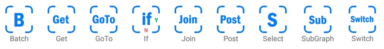
- Batch : Apply branch (bottom) pipeline to all detected objects and then progress to the next (right) module.
- DROP FAIL : If activated, deletes any objects that do not pass the branch pipeline detection
- GET : Loads variables saved by the Post module
- KEY : Select the name of the variable to be loaded
- GoTo : Jump to Join module in the graph.
- NAME : Enter the target Join module name
- If : Creates two possible paths for the algorithm based on a condition. If the conditional statement is true, it proceeds to the Y branch, if false, it proceeds to the N branch.
- KEY : Name of the variable to be the basis
- target : The name is specified as target
- name : The name assigned to the current target
- passed : Outcome of previous inspection is used (pass/fail)
- METHOD : Comparison method, same (==), different (!=), equal or bigger (>=), equal or smaller (<=), bigger (>), smaller (<)
- VALUE : Reference value for comparison
- KEY : Name of the variable to be the basis
- Join : Marks point where GoTo module points to.
- NAME : Enter the node’s name
- Post : Save the result of calculation up to now.
- KEY : Name of the variable to be saved
- VARIABLE : Variable(s) to be saved (You can save all variables by selecting all or only specific variables, and only the variables passed by the previous modules are displayed in the list.)
- Select : Select one of the detected objects, must be placed after a Detection class module.
- KEY: Selection criteria; either the detection score, size or camera reference position (X, Y, Z) of the objects
- METHOD : Selection method (object with either the biggest or smallest KEY are selected)
- ON RETRIEVE : If activated, run command ends here and Conty's retrieve command starts on that node. (The object selected once is erased and the next object is sequentially executed in the next command.)
- SubGraph : Loads and executes one of the saved graphs
- NAME : Name of the graph to be loaded (select from saved graph)
- Switch : If it can split into multiple options, it represents the branch of the pipeline.
- After connecting several Switch modules downward as many as the number of options, select the standard through the KEY variable in the top Switch module.
- Specify VALUE for each switch, execute pipeline connected to the right of the corresponding switch according to VALUE.
Info
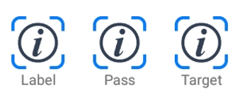
- Label : Names the currently detected object. When combined with modules such as Gripper and if, a name needs to be registered.
- NAME : Name it as typed text
- Pass : Forces the pass or fail of the currently detected object.
- STATE : Force selected state (pass or fail)
- Target : Specify the object to be detected. This is the same command as specifying the target to be detected by Conty. If this module is added, the target specified by Conty is ignored and the target specified by the module is detected. Remove after testing when used in combination with Conty.
- TARGET : Select the target
Segmentation

- DilateMask : Expand the detected mask
- SIZE DILATE : Adjust the value to expand the detected area
- ErodeMask : Reduce the detected mask
- SIZE ERODE : Adjust the value to reduce the detected area
- Fill : If there are many blank areas inside the detected area, fill the detected area. It also fills in the curved areas inward.
- GrabCut : Region segmentation algorithm. It takes about 1 second, but more accurately separates the object area around the currently detected area.
- ITERATION : Number of iterations of the algorithm. The more iterations, the more accuracy, but the longer the algorithm will take.
- RESIZE : Reduce the ratio to apply the algorithm. The smaller the image, the faster the algorithm, but the less accurate.
- SIZE CLOSE : Ignores any holes in the detected areas bigger than the set value and fills them
- SIZE DILATE : The range to apply the algorithm around the currently detected area (If it is too wide, it will be affected by other objects. If it is too narrow, it may not contain all objects.)
- MaskFromROI : Make a mask from the current region of interest.
- Polygon : Make a mask based on a set of vertices (x, y) passed by in a list of points named polygon
- RefineEdge : Detects borders in the image to refine the detected object area.
- CANNY MAX : Boundary lines with a larger variation than the parameters and setting values of the Canny algorithm are unconditionally detected.
- CANNY MIN : Boundary lines with a smaller variation than the parameters and setting values of the Canny algorithm are unconditionally ignored.
- EDGE LENGTH : The minimum length of valid borderlines. Set this value large to ignore noise.
- SIZE DILATE : The range to apply the algorithm around the currently detected area (If it is too wide, it will be affected by other objects. If it is too narrow, it may not contain all objects.)
- SIZE ERODE : The range to apply the algorithm inside the currently detected area (If it is detected as wider than the current real object, it is necessary to grab this larger value and resize it to fit inside the currently detected area.)
- TrackMask : Calculate velocity of the detected region and offset mask by expected motion offset.
- SCAN RANGE : The range to detect motion around the detected mask. (in pixels)
- MOTION DELAY : The expected motion delay to calculate corresponding offset. (ms)
- METHOD : The algorithm to calculate the optical flow of the image.
- WaterShed : Basic region segmentation algorithm
- SIZE DILATE : The range to apply the algorithm around the currently detected area (If it is too wide, it will be affected by other objects. If it is too narrow, it may not contain all objects.)
- SIZE ERODE : The range to apply the algorithm inside the currently detected area (If it is detected as wider than the current real object, it is necessary to grab this larger value and resize it to fit inside the currently detected area.)
Inspection
- CheckFeature : Inspect object with key features.
- BEST MATCH COUNT : The number of feature points to be used for a detecting single object. The smaller the value is, the easier it is to detect, with a loss of accuracy.
- DETECT NUM : Maximum number of detections.
- ERROR CUT : Maximum level of error to be considered as a valid detection. With a greater error-cut, you can detect more objects, with a loss of accuracy.
- MATCH THRESH : The maximum difference to be considered the same feature points. With greater match-thresh, you can find more feature point matches with less accuracy.
- TEMPLATE : The image of target object to be detected. Template should be saved in advance.
- CheckHSV : Check if the currently detected region for certain hue, saturation, Brightness values
- HUE, SATURATION, VALUE : The reference HSV values
- HUE : Color indication value ranging 0~360. The spectrum is in the order red-yellow-blue-purple.
- SATURATION : Saturation value ranging from 0~100.
- VALUE : Brightness value ranging from 0~100.
- MODE : Method for checking the region, take the average values of the area or check the center point.
- RANGE H, S, V : Allowed tolerance of HSV values (If it is within the range above or below the reference color value, it is displayed as normal.)
- TOUCH : Touch the screen to set the HSV reference values to the values of the touched area
- HUE, SATURATION, VALUE : The reference HSV values
- CheckLoc : Inspect the pixel location of detected region.
- X MIN, X MAX : The minimum and maximum values of X axis value.
- Y MIN, Y MAX : The minimum and maximum values of Y axis value.
- CheckRGB : Check the currently detected region for a color
- BLUE, GREEN, RED : Color in RGB values
- MODE : Method for checking the region, take the average values of the area or check the center point.
- RANGE B, G, R : Allowed tolerance of HSV values (If it is within the range above or below the reference color value, it is displayed as normal.)
- TOUCH : Touch the screen to set the HSV reference values to the values of the touched area
- CheckRadius : Inspect radius of detected area.
- INLIER RATIO : The minimum inlier ratio to pass the inspection.
- ITER COUNT : The number of iteration in RANSAC algorithm.
- R MIN, R MAX : The minimum and maximum radius.
- SAMPLE NUM : The number of points to sample from the edge contour.
- TOLERANCE : The maximum error for the inliers.
- CheckTemplate : The most basic template matching method for inspection. It assumes the size and orientation of the object is not different from the template.
- CONCORDANCE CUT : Minimum concordance rate to be detected.
- REF SIZE : The template is resized into REF SIZE. The smaller the size is, the faster the calculation is, but less accurate.
- TEMPLATE : The image of target object to be detected. Template should be saved in advance.
- Circularity : Check the circularity of the detected area
- CUT : If the roundness is higher than the set value, it is displayed as normal.
- CompareText : Compare and check text detected by OCR, ScanCode, etc.
- REGISTER : Save the currently detected text
- METHOD : Comparison method, equals (==), does not equal (! =), equal or bigger (> =), equal or less than (<=), greater than (>), less than (<)
- VALUE : Reference for comparison, selectable from saved text
- FitShape : Check if detected area fits a specific shape
- ASPECT CUT : Upper limit of aspect ratio if it is not a circle or square
- BURR LIMIT : Upper limit of pixels deviating from the reference shape
- SHAPE : Reference shape (currently only ellipses are supported)
- SqrtArea : Check the area of the detected area. The square root of the area is used as criterion. If the detected area falls within the range within the range based on the REF SIZE, it is determined as normal.
- RECORE : Record the square root of the current mask width
Orientation
- DirectTo : Set the orientation of an object based on a reference point inside or around the object. Find the reference point by adding an algorithm pipeline to the branch to search for the reference point.
- ALIGN OBJECT AXIS : Indicate which object axis should be aligned in the direction of the reference point, X-axis (red) or Y-axis (green).
- CROP MASK : If activated, cut around the current detection area and search by reference point (Improving unnecessary computation speed)
- MatchEdge : Find the position and angle where the input image and the sample image match based on the borders on the image. Any template-related module should be applied in advance (i.e. MatchFeature, MatchRPT, MatchTemplate
- CANNY MAX : Boundary lines with a larger variation than the parameters and setting values of the Canny algorithm are unconditionally detected.
- CANNY MIN : Boundary lines with a smaller variation than the parameters and setting values of the Canny algorithm are unconditionally ignored
- GAIN ROT : Correction rate for object angle (if the value is too big, correct angle might not be found)
- GAIN XY : Correction rate for object position (if the value is too big, correct position might not be found)
- ITER NUM : The number of iterations the algorithm takes (the more iterations, the more accuracy, but the more time it takes)
- PCA : Estimate the object angle based on the long axis of the detected area using Principal Component Analysis.
- ALIGN OBJECT AXIS : Indicate which object axis should be aligned in the direction of the longest object axis, X-axis (red) or Y-axis (green).
- ALIGN CAM AXIS : Choose up, down, left, right or the prior calculated direction as the direction of the aligned axis.
- DIRECTED OBJECT : Indicates whether the object geometrically has a direction, i.e. a triangle. The axis will be aligned with the pointed side.
- Rotate : Set angle of the X-axis (red) of the object
- ANGLE : Value of the angle
- REFERENCE : Set the reference axis to which the angle is set, either a previously calculated angle (relative) or to the normal X-axis (absolute).
Pose

- FitPlane : Calculate the 3D position of a detected object by projecting it on the work plane
- FLOOR OFFSET : Vertical offset from the work plane (in mm)
- Silhouette2D : Match detected object with a 3D model to estimate the pose of the object. A CAD file with the same name as the detected object’s name must be added to CAD LIST. It is assumed that the object is lying on the work plane, with its Z-axis perpendicular to the work plane.
- AVAILABLE CADS : List of available 3D models. Select a model and press ADD TO LIST to register it (new models can be uploaded via the DB button in the top right corner)
- CAD LIST : List of currently registered 3D models
- FLOOR OFFSET : Vertical offset from the work plane (in mm)
- IOU CUT : Lower limit of concordance with the silhouette to be considered a successful estimation (Posture estimation fails if it matches to a lower level than the set value)
- ROT RANGE : Range of angles the object can rotate (Precise posture search within a given angle up/down range)
- TRACK ITER : Posture estimation resolution (more iterations give better accuracy but is slower)
- TRACK SCALES : Posture estimation repetitions (Narrow the range based on the results of one estimate and perform estimation again in the narrowed range)
Data

- Load : Loads a previously saved operation result
- FILENAME : Name of the file to be loaded
- IMAGE ONLY : If activated, loads only the image from the saved result
- LoadImage : Loads a previously saved image
- FILENAME : Name of the image to the be loaded
- Save : Save the operation result to local disk.
- CONDITION : Condition for saving; always or only when objects pass/fail the inspection
- FILENAME : Name of the file to be saved
- MAX COUNT : Maximum number of files to be saved
- SUFFIX : When storing multiple data files, a unique suffix can be added to the file, either an increasing number or date and time.
- SaveImage : Save the current image to the local disk. The saved image is used as a TEMPLATE in a detection algorithm using a template.
- FILENAME : Name of the image to be saved
Workspace

- CheckWorkspace : Check whether the object is inside the workspace
- SetWorkspace : Load a saved workspace
- WORKSPACE : Select the workspace to be loaded
Action
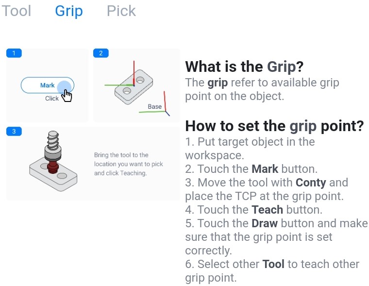
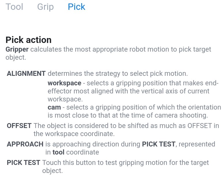
- Gripper : Teach grasping action for objects.