CORE Installation
CORE structure
Each CORE module consists 5 hardware parts:
- 1 Harmonic drive
- 1 Motor
- 1 Magnetic brake
- 1 Absolute encoder: magnetic disk and encoder board
- 1 Driver: controller board and power board
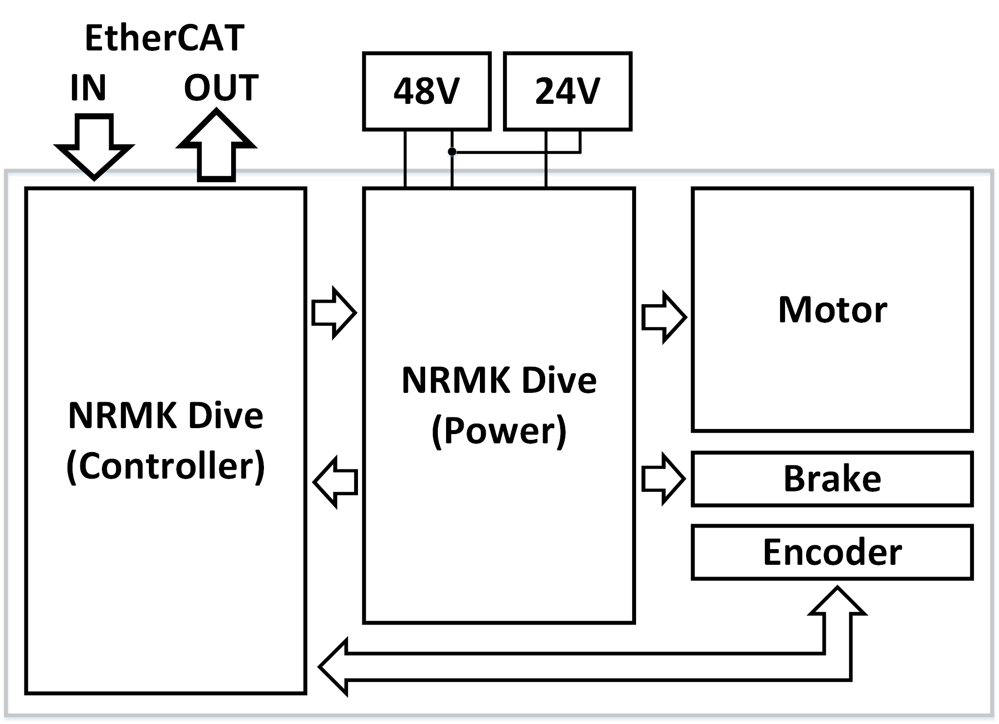
Figure 1. CORE module - Block diagram
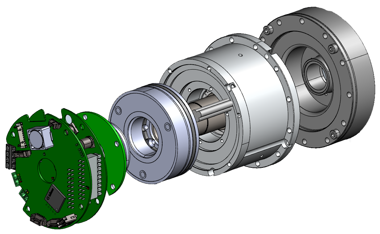
Figure 2. CORE100 - Mechanical structure
Wiring guide
Motor driver
CORE’s driver includes controller board and power board. Two boards are connected in sandwich style by board-to-board headers. Several signals are wired to controller board while other are connected to power board. Controller board is commonly used for all CORE models. Power board will be different depends on CORE’s power.

Figure 3. CORE module driver
There are two classes of connection:
-
Internal connections: control signal, feedback signals…from Driver to/from CORE’s components, such as:
- Motor 3 phases connection
- Brake lines
- Encoder signals
-
External connections: interaction interfaces between user and CORE module, such as:
- 48V main power supply
- 24V brake power supply
- EtherCAT IN and OUT ports
Motor driver connection
Connector on CORE100/CORE200 driver
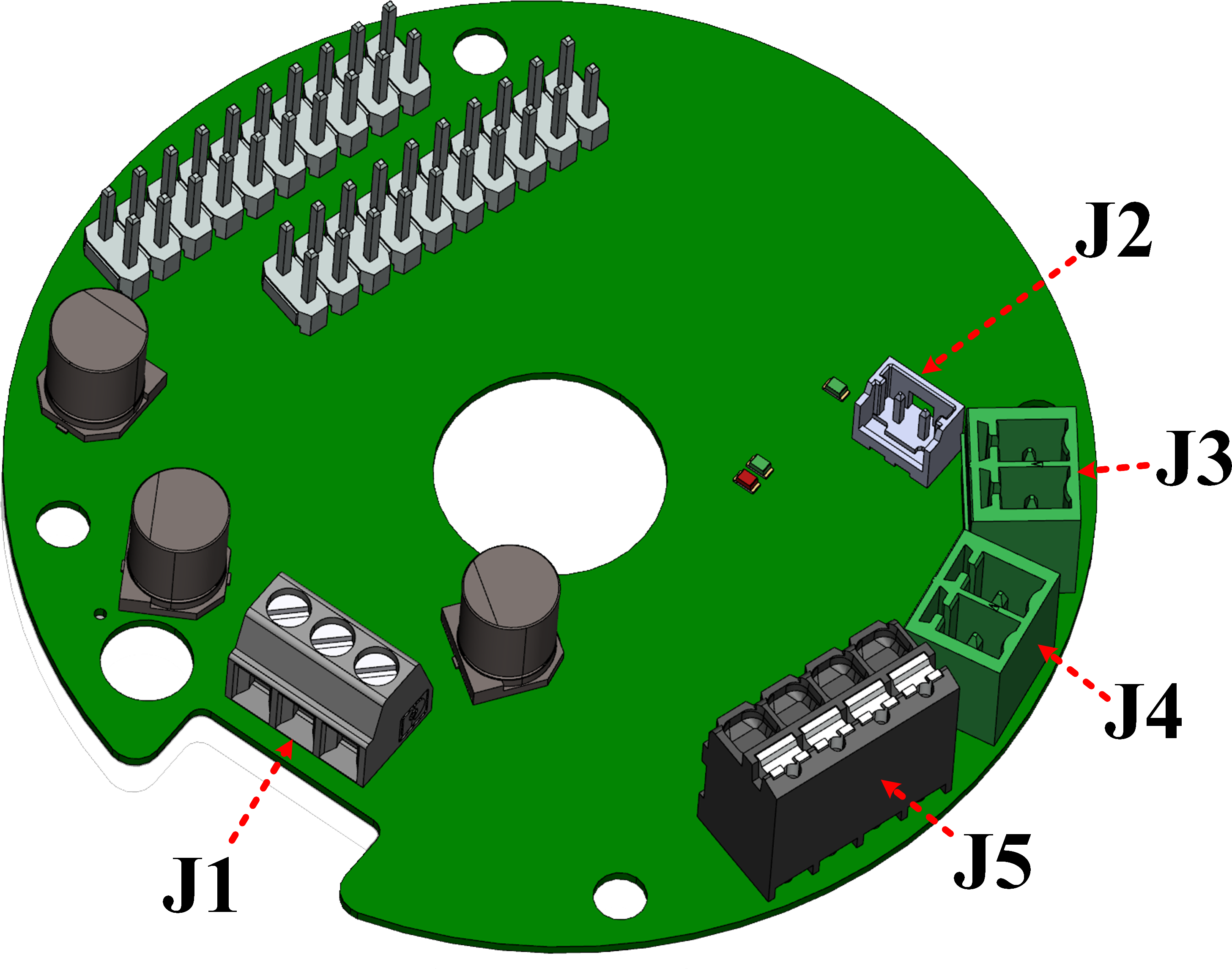
 Figure 4. CORE100/CORE200 connectors
| No. | Connector | Number of pin | Description | Internal/External |
|---|---|---|---|---|
| 1 | J1 | 3 | Motor phases connector | Internal |
| 2 | J2 | 2 | Brake lines | Internal |
| 3 | J3 | 2 | 48V power input | External |
| 4 | J4 | 2 | 48V power output | External |
| 5 | J5 | 4 | 24V, Brake free input-output | External |
| 6 | J7 | 8 | Encoder | Internal |
| 7 | J8 | 5 | EtherCAT IN port | External |
| 8 | J9 | 9 | EtherCAT OUT port | External |
| 9 | J10 | 6 | CAN port | Unused |
| 10 | J11 | 4 | USB port | Unused |
| 11 | J12 | 2 | Motor temperature sensor | Unused |
Table 1. CORE100/CORE200 connector description
Connector on CORE500 driver
 Figure 5. CORE500 connectors
| No. | Connector | Number of pin | Description | Internal/External |
|---|---|---|---|---|
| 1 | J1 | 3 | Motor phases connector | Internal |
| 2 | J2 | 2 | Brake lines | Internal |
| 3 | J3 | 2 | 48V power input | External |
| 4 | J4 | 2 | 48V power output | External |
| 5 | J5 | 2 | 24V, Brake free input | External |
| 6 | J6 | 3 | 24V, Brake free output | External |
| 7 | J7 | 8 | Encoder | Internal |
| 8 | J8 | 5 | EtherCAT IN port | External |
| 9 | J9 | 9 | EtherCAT OUT port | External |
| 10 | J10 | 6 | CAN port | Unused |
| 11 | J11 | 4 | USB port | Unused |
| 12 | J12 | 2 | Motor temperature sensor | Unused |
Table 2. CORE500 connector description
Motor and brake connection
Below diagram shows connection between CORE driver and Motor & Brake:
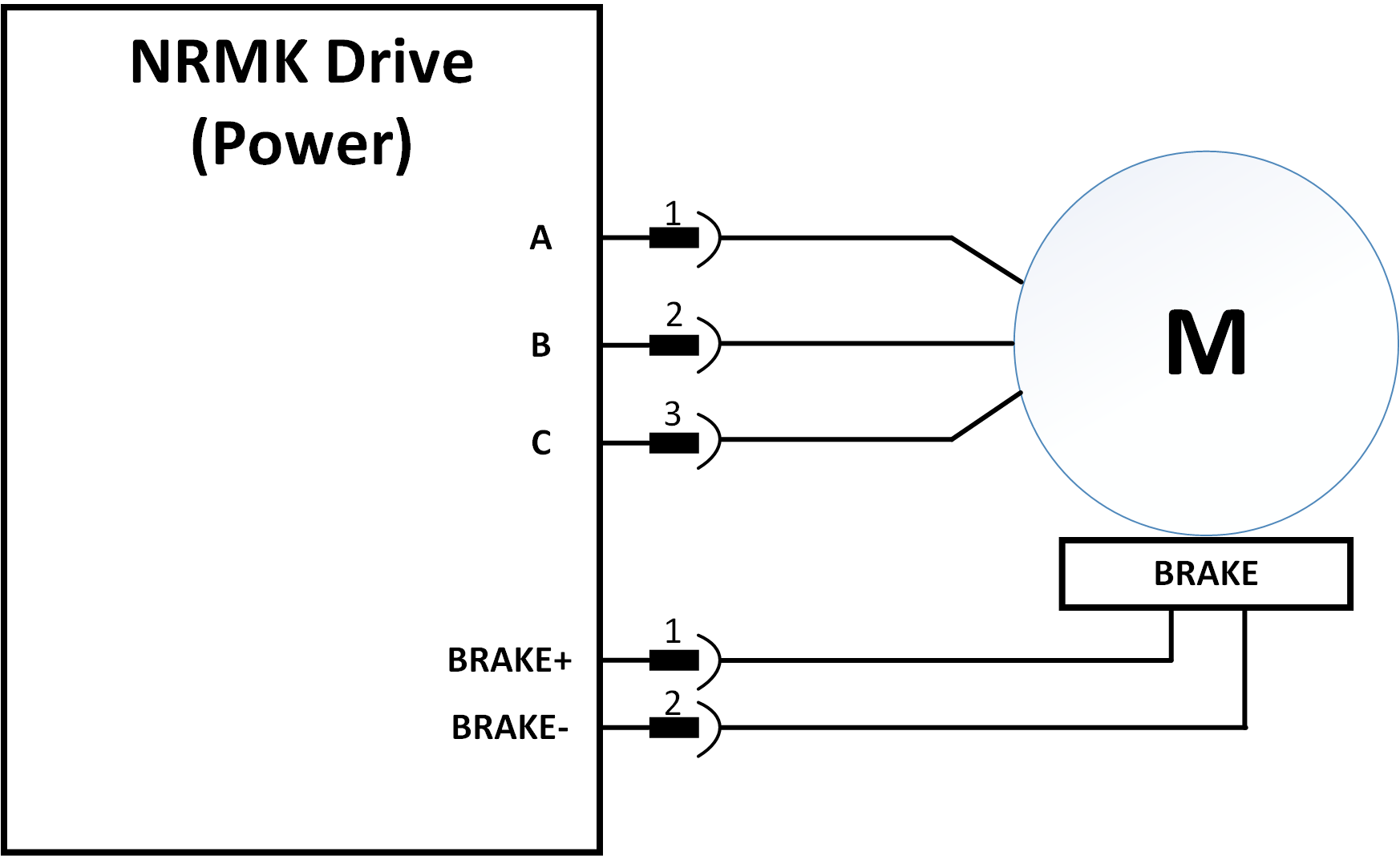 Figure 6. Motor and Brake connection diagram
Motor connection 3 motor phase terminals are directly connected to power board in follow order:
| Pin number (J1) | Motor phase |
|---|---|
| 1 | U |
| 2 | V |
| 3 | W |
Table 3. Motor connector pins
Brake connection
| Pin number (J2) | Brake line |
|---|---|
| 1 | Br+ |
| 2 | Br- |
Table 4. Brake connector pins
Motor and Brake connector on PCB
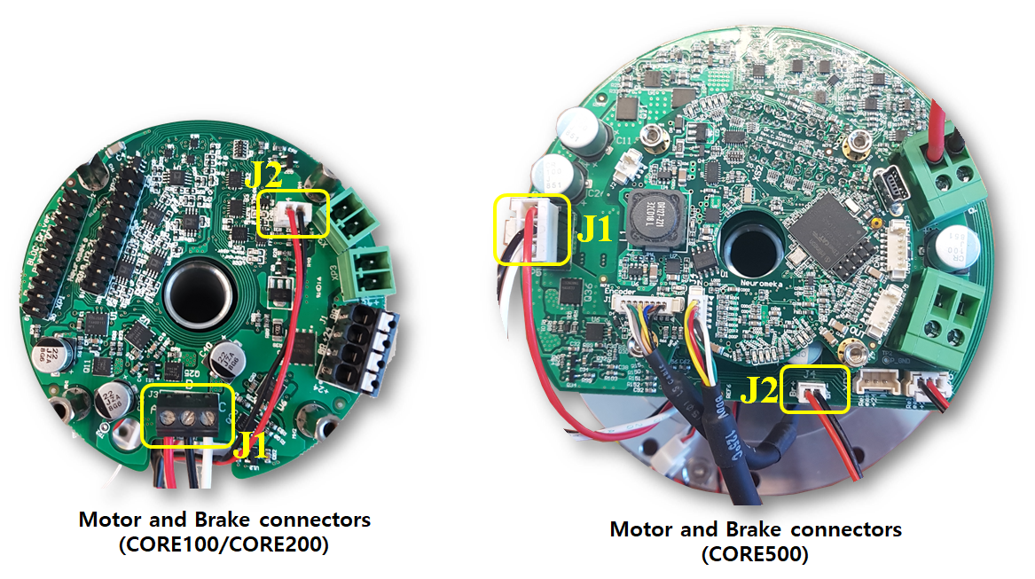 Figure 7. Motor and Brake connectors
Encoder connection
Absolute encoder connects to control board (J7) by a twised pair cable. Please note that PRESET line which is used to preset multi-turn data is not connected. Below diagram describes connection between encoder and control board.
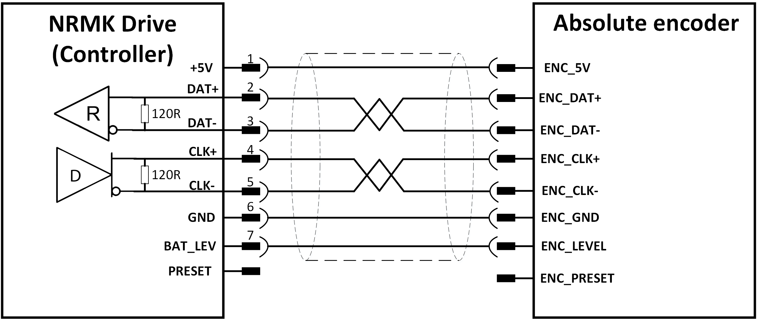 Figure 8. Encoder connection diagram
Encoder connector pins:
| Pin number (J7) | Encoder line |
|---|---|
| 1 | 5V supply |
| 2 | DATA+ |
| 3 | DATA- |
| 4 | CLOCK+ |
| 5 | CLOCK- |
| 6 | GND |
| 7 | Battery level |
| 8 | PRESET (unused) |
Table 5. Encoder connector pins
Encoder connector on PCB:
 Figure 9. Encoder connector
Power supply (PS)
In order for CORE operation, two power sources are needed:
- Main Motor and driver power supply is 48V
- An additional 24V source is needed for brake operation
Two power sources must has common GND. User should select main 48V PS so that its current is at least 1A larger than rated current of CORE module. The supply current of 24V source must be larger than 0.5A.
Power supply connection is described in below diagram:
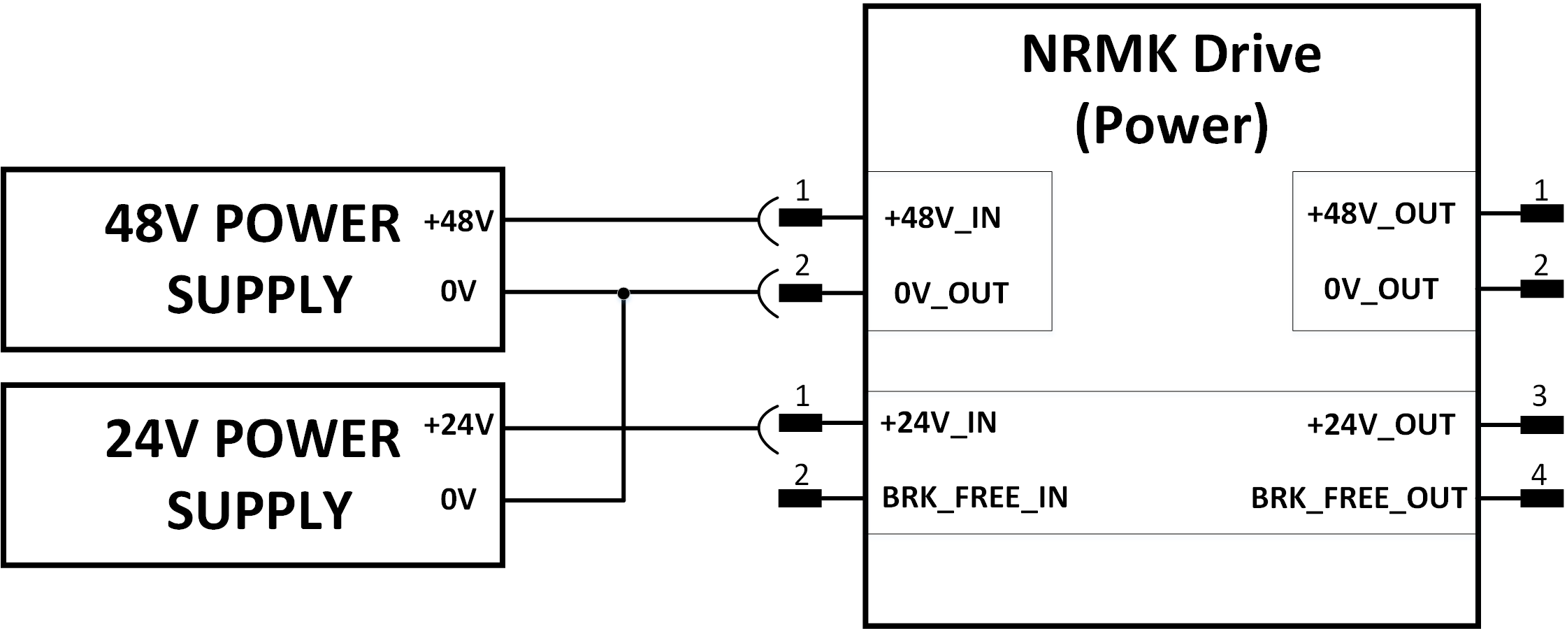
Figure 10. Power supply connection diagram
48V Power supply connector pins:
| Pin number (J3, J4) | Power line |
|---|---|
| 1 | +48V |
| 2 | 0V |
Table 6. 48V Power supply connector pins
Brake power supply connector pins (CORE100/CORE200):
| Pin number (J5) | Power line |
|---|---|
| 1 | +24V IN |
| 2 | Brake free IN |
| 3 | +24V OUT |
| 4 | Brake free OUT |
Table 7. Brake power supply connector pins (CORE100/CORE200)
Brake power supply connector pins (CORE500):
| Pin number (J5, J6) | Power line |
|---|---|
| 1 | PE |
| 2 | +24V |
| 3 | Brake free |
Table 8. Brake power supply connector pins (CORE500)
Power supply connector on PCB:
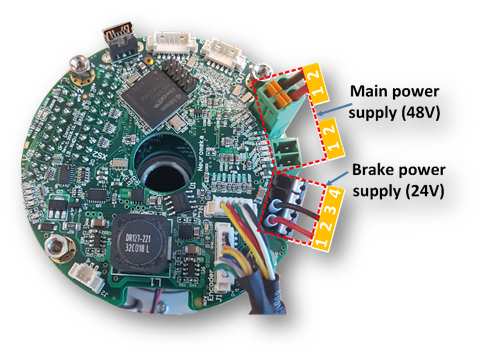 Figure 11. Power supply connector on CORE100/CORE200
 Figure 12. Power supply connector on CORE500
EtherCAT Connection
There are 2 EtherCAT connectors on controller board for input and output signals. Each has 5 pins as Tx+/Tx-, Rx+/Rx- and shield.
EtherCAT IN is connector to previous device (or master) and EtherCAT OUT is connected to next device or to master in redundancy topology.
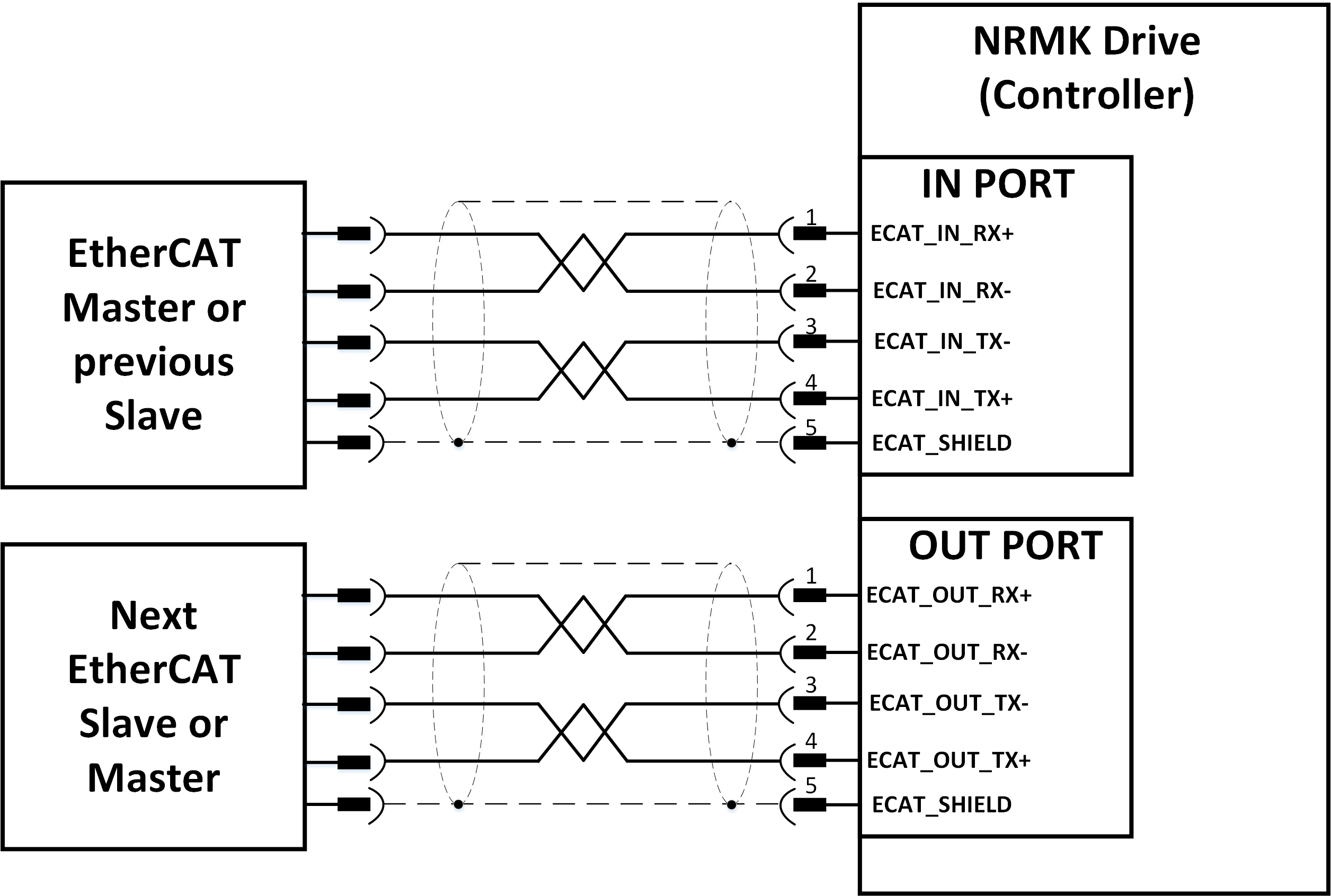 Figure 13. EtherCAT connection between CORE and other ethercat devices
Notice:
Do not switch EtherCAT ports, e.i. IN port becomes OUT port and vice versa.
If two EtherCAT ports are switched, devices still work but network topology will be changed.
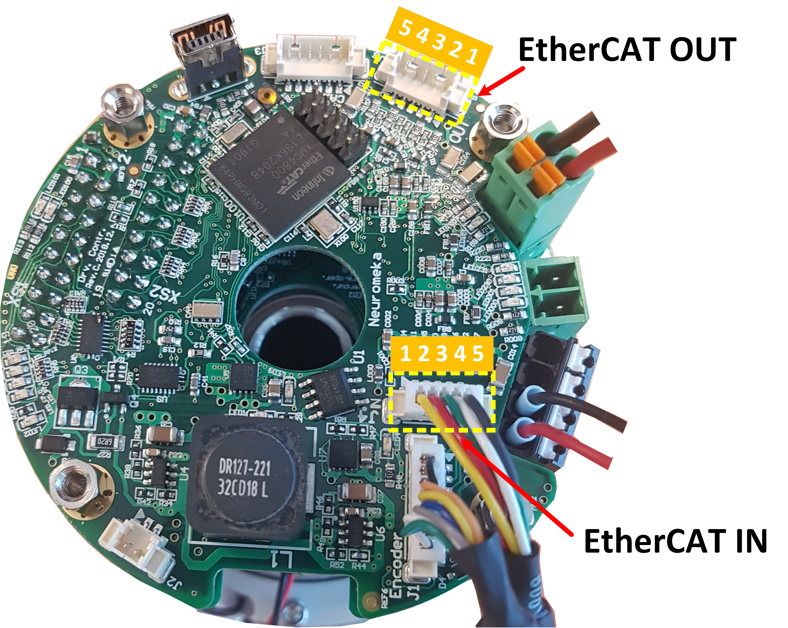 Figure 14. EtherCAT connector on controller board
| Pin number (J8, J9) | Signal |
|---|---|
| 1 | Rx+ |
| 2 | Rx- |
| 3 | Tx- |
| 4 | Tx+ |
| 5 | Shield |
Table 9. EtherCAT connector pin description
