Basic communication of IndyCB and STEP
This chapter describes how to use SmartIO that can control Digital I/O and Analog I/O equipped in control box (IndyCB) and STEP. SmartIO is a software element that makes it easy to utilize Digital I/O and Anaolog I/O through Conty, ModbusTCP, IndyDCP, and Shared Memory without any additional setup.
Abbreviation
- Digital Input, Digital Output: DI, DO
- Digital Input/Output: DIO
- Analog Input, Analog Output: AI, AO
- Analog Input/Output: AIO
I/O ports of IndyCB
The below figure shows the I/O port configuration of IndyCB (control box). It consists of 32 channels of DIO, 8 channels of 5V DIO, and 4 channels of AIO.
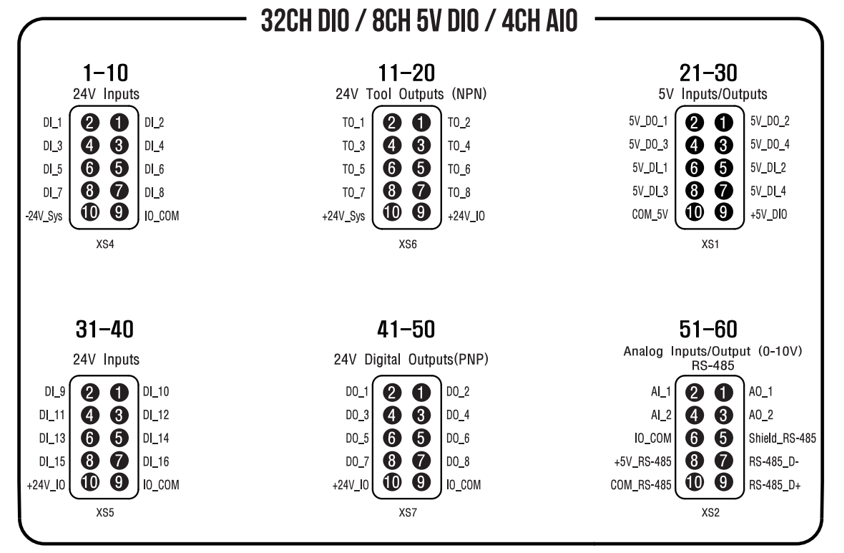
I/O port configuration of Indy Control Box
- 16ch 24V DI
- 16ch 24V DO (NPN Tool Outputs and PNP DO)
- 8ch 5V DI, 8ch 5V DO,
- 2ch 0-10V AI
- 2ch 0-10V AO
Digital I/O ports of STEP GPIO
Because the old-model Control Box before Indy7 does not have I/O ports itself, it needs GPIO port of STEP for digital I/O communication 1.
The picture below shows the I/O ports of STEP, and you can see the 16-pin GPIO port.

I/O ports of STEP
The pin numbers of the GPIO are shown in the figure below. Indy Framework enables to use 7 channels of 5V DI and 7 channels DO among 14-pins of STEP GPIO as shown in the table below.

| Pin | GPIO Mapped Name | Pin | GPIO Mapped Name |
|---|---|---|---|
| 1 | Safety Out | 14 | STEP_DO_06 |
| 2 | STEP_DO_02 | 15 | STEP_DO_05 |
| 3 | STEP_DO_01 | 16 | STEP_DO_04 |
| 4 | STEP_DO_00 | 17 | STEP_DO_03 |
| 5 | Safety In | 18 | VCC |
| 6 | STEP_DI_06 | 19 | VCC |
| 7 | STEP_DI_05 | 20 | GND |
| 8 | STEP_DI_04 | 21 | GND |
| 9 | STEP_DI_03 | 22 | GND |
| 10 | STEP_DI_02 | 23 | GND |
| 11 | STEP_DI_01 | 24 | GND |
| 12 | STEP_DI_00 | 25 | GND |
| 13 | NC |
GPIO Pin Mapping on STEP
Digital I/O control using SmartDIO
SmartDIO is a software element that makes it easy to use digital I/O ports of IndyCB and STEP through mapping each pin. There are 32 Input and Output each from 00 to 31. The DIO port and pin information mapped into SmartDIO's each number is shown in the table below.
SmartDIO Port & Pin Mapping
| SmartDIO Index | Mapped Port Name | Pin Name |
|---|---|---|
| SmartDI_00-15 | [CB] 24V Digital Inputs Port | DI_1-16 |
| SmartDI_16-19 | [CB] 5V Digital Inputs Port | 5V_DI_1-4 |
| SmartDI_20-26 | [STEP] 5V Port0 | STEP_DI_00-06 |
| SmartDO_00-07 | [CB] 24V NPN Tool Ouputs Port | TO_1-8 |
| SmartDO_08-15 | [CB] 24V PNP Digital Ouputs Port | DO_1-8 |
| SmartDO_16-19 | [CB] 5V DO Port | 5V_DO_1-4 |
| SmartDO_20-26 | [STEP] 5V Port1 | STEP_DO_00-06 |
SmartDIO has 32 I/O each, and there are unused numbers made for future scalability. When using IndyCB, all ports marked as [CB] are available, but STEP GPIO cannot be used because it is used for internal power control. When using old-model control box that has no I/O board or STEP only, the ports marked as [STEP] are only available.
Note
The value of SmartDIO is either HIGH(1) or LOW(0) same as normal DIO uses.
Analog I/O control using SmartAIO
SmartAIO is also a software element that makes it easy to use analog ports of IndyCB through mapping each pin; STEP GPIO does not support AIO. There are 4 Input and Output each from 00 to 03. The AIO port and pin information mapped into SmartAIO's each number is shown in the table below.
SmartAIO Port & Pin Mapping
| SmartAIO Index | Mapped Port Name | Pin Name |
|---|---|---|
| SmartAI_00-01 | [CB] 0-10V Analog Inputs Port | AI_1-2 |
| SmartAO_00-01 | [CB] 0-10V Analog Outputs Port | AO_1-2 |
SmartAIO has 4 I/O each, but does not use all numbers as same as SmartDIO.
Note
The value of SmartAIO is between integer 0 and 10000. The value of 0 is 0V and 10000 is 10V.
Usage in Conty
In Conty which is Neuromeka's teach pendant, users can see Port&Pin Map of SmartIO shown in the picture below. Also, users can test DIO and AIO in Servo/SmartIO menu. With this feature, users can control DIO and AIO with robot motion programming (Please refer to "Indy7 User Manual" for a detailed description).

SmartIO Mapping Guide UI in Conty
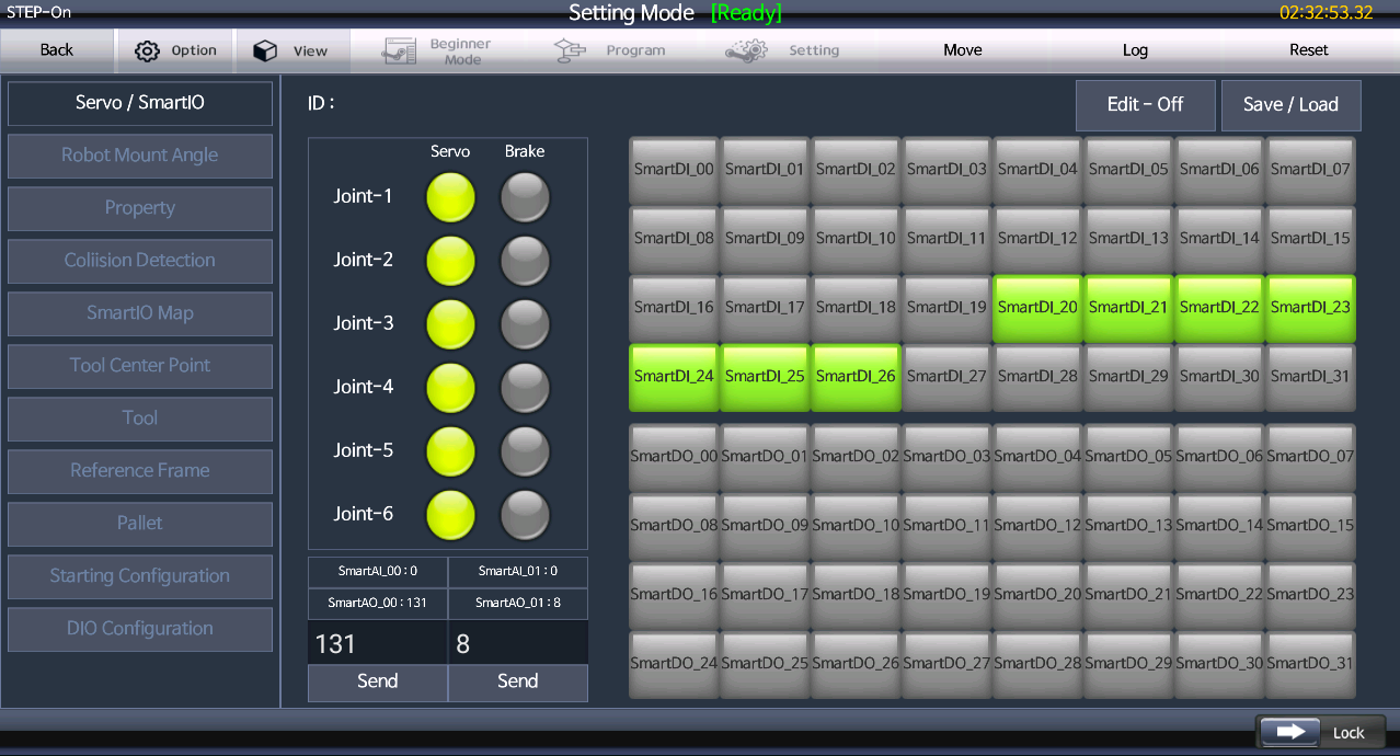
SmartIO control panel in Conty
Usage in other ways
DIO and AIO control using SmartIO is supported not only in Conty but also in ModbusTCP and IndyDCP. It is also supported by SharedMemory API for SW developers, so that SW engineers can easily control I/O. Please refer to the links below for related documents.
-
In case of IndyRP, GPIO port can be directly used because STEP is located outside of the control box. For Indy3/5/10, GPIO port of control box is connected to STEP's one, so it can be used. ↩
