Basic Tutorial
PD controller for Robot Manipulator
This section provides a basic tutorial to help users understand. In particular, this tutorial provides an example of implementing a joint-space PD controller using IndySDK.
In robotics, a joint-space PD set-point regulation control is well known to guarantee the passivity and asymptotic stability of multi degree-of-freedom robot manipulators. For more details, please refer to the following review paper.
Create a Component of IndySDK in Eclipse.
- Execute the Eclipse IDE using Eclipse icon in NRMK Launcher.
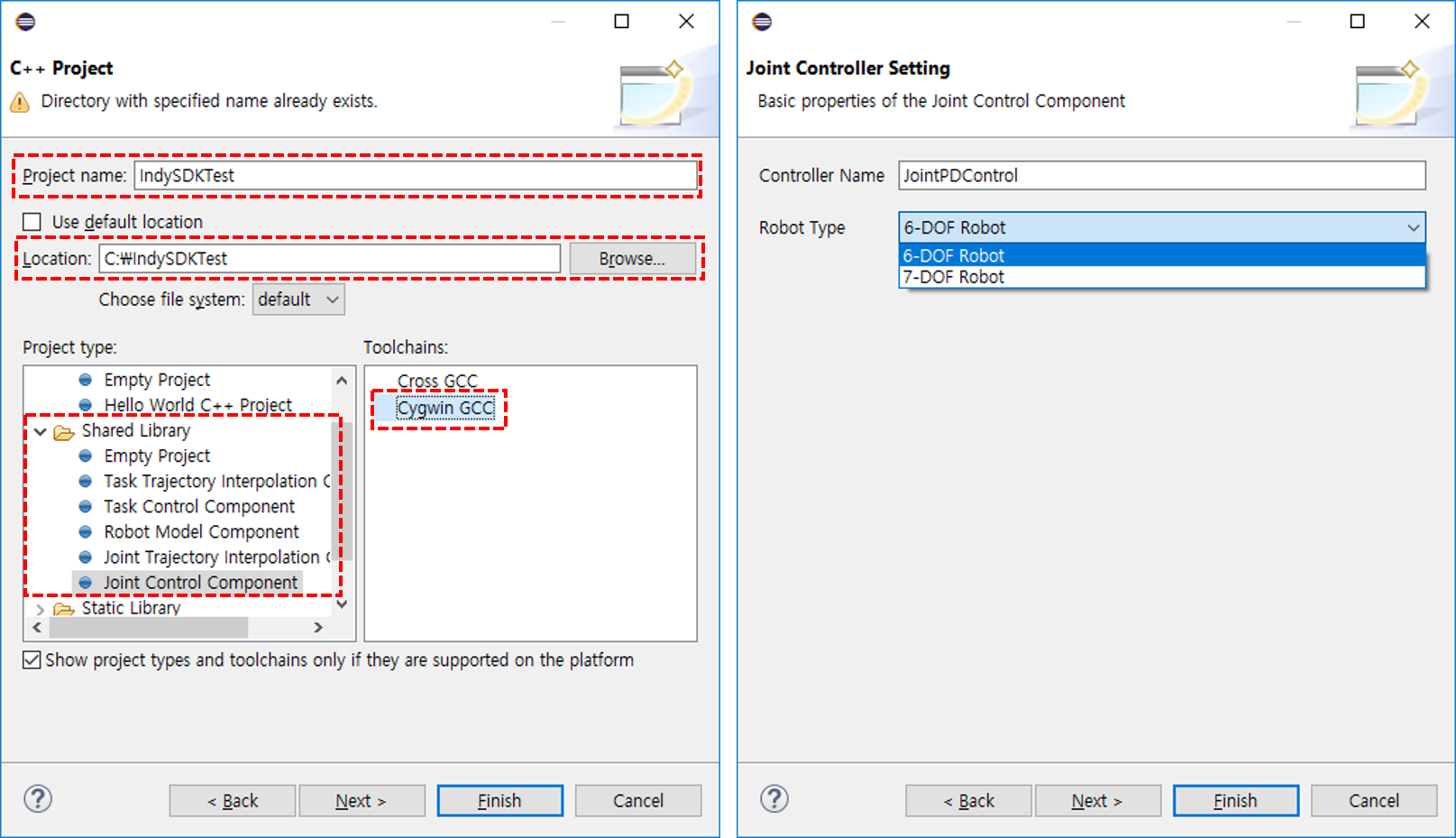
- After the Eclipse IDE launched, enter File > New Project > C++ Project > C++ Managed Build and click the Next button
- Fill in Project name and select Shared Library > Joint Control Component as Project type
- Select Cygwin GCC as Toolchains and click the Next button
- Fill in Controller Name, select the robot type (6-DOF for Indy7, 7-DOF for IndyRP2) and click the Finish button
Joint Control Component project generation
When the project created, the header and cpp files including project's template are automatically created.

The template of Joint Control Component (Automatically Generated)
Right-click on the project and set the release to Active via Build Configuration > Set Active > Release.

Set Build Configuration to Release
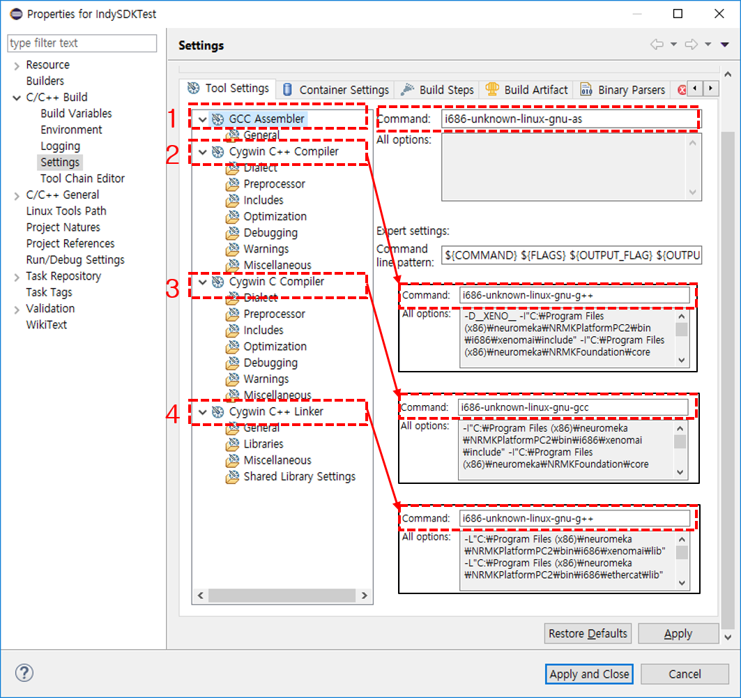
Right-click on the project and set the Command as shown in below via Properties > C/C++ Build > Settings
- GCC Assembler Command: i686-unknown-linux-gnu-as
- Cygwin C++ Compiler Command: i686-unknown-linux-gnu-g++
- Cygwin C Compiler Command: i686-unknown-linux-gnu-gcc
- Cygwin C++ Linker Command: i686-unknown-linux-gnu-g++
In project properties, click Build Artifact tap and Change Artifact Extension from dll to comp. Artifact Type should be Shared Library. As default, the name of artifact is same with project's one but, in this example, we changed it to JointGravityPDControl

Note
In case user change the artifact name, the code at the bottom of the .cpp code needs to be modified.
- typedef JointPDControl IndySDKTest; -> typedef JointPDControl JointGravityPDControl;
- POCO_EXPORT_CLASS(IndySDKTest) -> POCO_EXPORT_CLASS(JointGravityPDControl)
You are now ready to use Joint Control Component. As shown in Table, the Joint Control Component is activated in three modes. The first is the preparation stage, where the joint-space control is used to maintain robot's current position. Second, the joint-space control is used for trajectory tracking. Finally, a gravity compensation control is used for direct teaching. In Joint Control Component, the user need to consider two types of controllers (i.e., joint-space and gravity compensation controllers).
Implement Gravity Compensation
The gravity compensation controller is activated in direct teaching mode as described above and must be implemented in the computeGravityTorq function.
1 2 3 4 5 6 7 8 9 10 11 12 | |
Here is an example of using the idyn_gravity() function of the robot object to find the gravity torque of the robot and input it as a control input (feedforward).
Implement Joint-Space Control
The joint space controller is active when the robot is in the joint move or ready state, and must be implemented in the computeControlTorq function. In this example, we implement gravity compensation control and PD control simultaneously.
First, in the class definition in the JointPDControl.h, declare the typedef typename ROBOT :: JointMat JointMat as shown below.
1 2 3 4 5 6 7 8 9 10 | |
And then, implement the gravity compensation PD controller in the computeControlTorq function in the JointPDControl.cpp file as shown below.
1 2 3 4 5 6 7 8 9 10 11 12 13 14 15 16 17 18 19 20 21 22 23 24 25 26 27 28 29 30 31 32 33 34 35 36 37 38 39 40 41 42 43 44 45 46 47 48 49 50 51 52 53 54 55 | |
Gravity torque is calculated using inverse dynamics. And joint space PD controller is calculated by using qDesired and q, qdot of robot object. Then, the PD controller and joint torque value are added to update the final input torque.
Build and Run
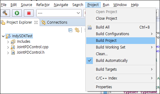
Now build the project. Click the project in Project Explorer and click Project > Build Project.
When the build is complete, a component file (shared library) is generated in the release directory.

Copy the generated component file (JointGravityPDControl.comp) to STEP's /home/user/release/LeanDeployment/Component directory. Then write the name of the component in the JSON configuration file. Please refer to Configure for JSON configuration file format and execution.
Use Indy7DControlTask_sim.so to run in simulation mode, and use the other default components except the Joint Controller Component. In the JSON configuration file, just replace the JController component with the newly built component as shown below.
1 2 3 4 5 6 7 8 9 10 11 12 13 14 15 16 17 18 19 20 21 22 23 24 25 26 27 28 | |
Run the robot with a command below in /home/user/release/LeanDeployment directory.
1 | |
Now, we can verify the performance of the PD controller using conty in the simulation. The developed joint space controller and gravity compensation controller are operated in the following three cases.
- First, the gravity compensation controller works in Direct Teaching

- Second, the PD controller acts as a joint space controller in motion command (Home Position and Zero Position).

- Finally, the PD controller works to follow the trajectory in jointMove. Conty makes it easy to generate the jointMove trajectory used for verifying the control algorithm.

Warning
Since the PD control gains in this example are determined randomly, the actual robot may not be controlled properly.
Gain Tuning
In the above example, we set the gain value directly in the controller (computeControlTorq). For convenience, we can use Conty for gain tuning without building a new component. If you touch Options > Virtual keyboard in Conty, the following screen will be appeared.
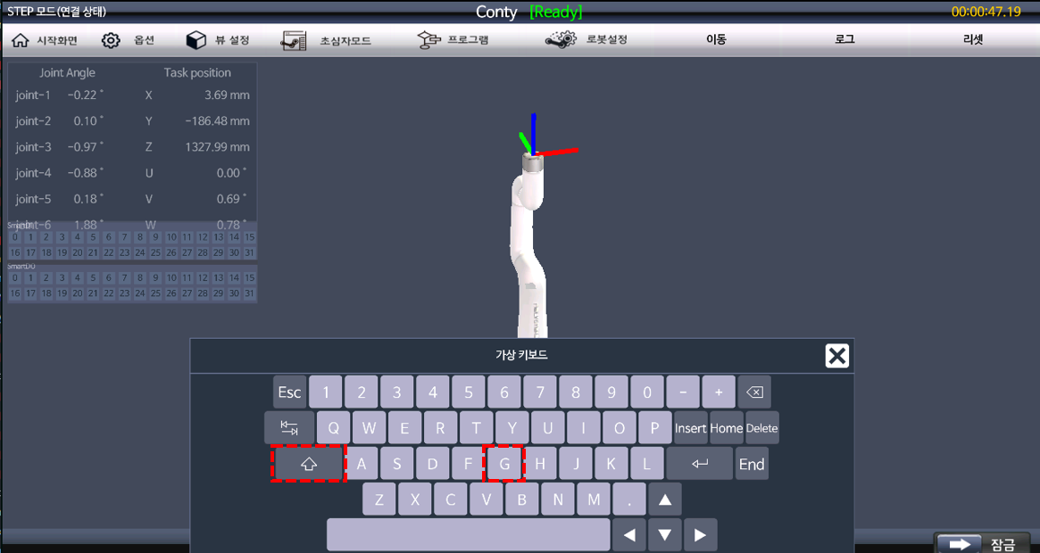
Pressing the capital 'G' will call the auto-generated setGains function from the Joint Controller Component template. So, if we make setGains function to read gains from external files, gain tuning will be set immediately without building a new component.
Assuming that the user-defined controller uses four control algorithms, write the setGinas function like the following pseudo code.
1 2 3 4 5 6 7 8 9 10 11 12 13 | |
After implementing the code for the reading of the gain values from an external file (txt, json, xml, etc.), assign it to the member variable. This allows the user to modify the gain value of an external file, and then update the gain value when requesting an update from Conty.
Data Logging
The following is the method for logging the data. With data logging, real-time control data, such as joint angles, joint speeds, taskspace position, and taskspace speeds, as well as user defeined data, can be saved to a file.
In this example, we will show the data logging for joint angle (q), joint angular velocity (qdot) and input torque (tau) calculated internally by IndySDK. From the code that implements gravity compensation PD control, data logging classes are added.
The full code can be found in git repository above.
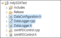
- DataLogger class for logging real-time data is added
- The data information to be acquired is declared in DataConfiguration.h as follows.
1 2 3 4 5 6 7 8 9 10 11 12 13 14 15 16 17 | |
The DataLogger class is implemented in DataLogger.h and DataLogger.cpp. BUFF_SIZE declared in DataLogger.h specifies the size of the buffer to store data for 5 seconds based on 4kHz control cycle. SAMPLE_LOG_FILE indicates the path and file name where the log file will be saved.
1 2 | |
Non-real-time thread is used for riting data stored in the buffer to a file at a specific timing. It inherits Runnable class provided by Poco which is 3rd party library included automatically when the IndySDK is installed.
1 | |
The member variable updateLoggedData(.) is used for collecting the real-time data into the buffer. In this case, we implemented a circular buffer that initializes the buffer index to 0 when it reaches the final value.
1 2 3 4 5 6 7 8 9 10 11 12 13 14 15 16 17 18 19 20 21 22 | |
Add the updateLoggedData function in the computeControlTorq() function that implements the PD controller. In this example, the data stored in the buffer is written to the file every 10 seconds (LOG_DATA_SAVE_PERIOD = 10 * 4000).
1 2 3 4 5 6 7 8 9 10 11 12 13 14 15 16 17 18 19 20 21 22 23 24 25 26 27 28 29 | |
The thread of the DataLogger class that inherits Runnable is implemented in the run() function.
The data in the circular buffer is written to a file when the Trigger event occurs.
1 2 3 4 5 6 7 8 9 10 11 12 13 14 15 16 17 18 19 20 21 22 23 24 25 26 27 28 29 30 31 32 33 34 35 36 37 38 39 40 41 42 43 44 45 46 47 48 49 50 51 52 | |
