Ethercat operation
Overview
CORE module is compliant with CiA402 CANopen profile for motion, implemented over EtherCAT so called CoE (CANopen over EtherCAT). In current FW revision (R1.10), only ‘Cyclic Synchronization Torque’ (CST) mode is supported. Other operation modes like velocity, velocity control should be obtained on application level In CST mode, CORE supports maximum update rate from master up to 12 kHz. Internal torque controller’s gain set has been tuned for each type of module. Advanced user can update these gains via EtherCAT SDO CORE supports firmware update via EtherCAT FoE (File over EtherCAT).
General EtherCAT device information
Device identity:
- Vendor ID - 0x0000089a: Neuromeka EtherCAT vender ID
- Product code - 0x30000000: Neuromeka motion device
Supported protocols:
- CoE: standard CANopen over EtherCAT protocol
- FoE: standard File over EtherCAT, used for driver’s firmware updating
CoE details:
- SDO enabled and complete access: user can completely access available objects via SDO
- Do not support PDO assign and configuration: PDO mapping is fixed, can’t be changed by user
- Enable LWR: master can read/write PDO data in same EtherCAT datagram
Distributed clock (DC):
- DC is a feature of EtherCAT that synchronize all EtherCAT slave devices and EtherCAT master within a small tolerant (~100ns)
- Neuromeka CORE support 64-bit DC clock
- In CST mode, module will operate regardless DC is enabled or disabled
SDO access
User can completely access drive variables defined by CiA402 via SDO. SDO objects are classified into two groups:
- Original function list: this group includes CiA402 standard objects which are used as their defined functions. It is noted that not all objects in this list are updated (some objects are always zero).
- Alternative function list: several objects are utilized for other functions like driver temperature data, module setting, module calibration, debug…
The completed list of objects are summarized in 2 tables in: Neuromeka_CompleteSDO_List.pdf
Original function object list:
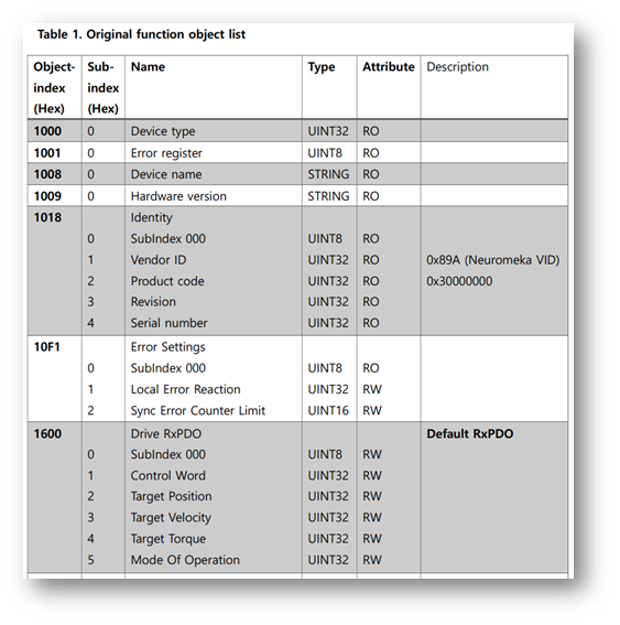 Figure 1. Original function object list
***Alternative function object list:***
Figure 1. Original function object list
***Alternative function object list:***
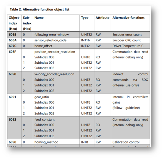 Figure 2. Alternative function object list
> ***Index***: standard index of object, in hexadecimal
> ***Sub-index***: each object may have several sub-objects, this is index of each sub-object exist in this object
> ***Name***: standard object name, it tells object function
> ***Type***: data type of an object
> ***Attribute***: access right in OP mode
> ***Description***: more explanation for object
--------------------------------
##Slave process data (PDO)
PDO data is cyclically sent/received between master and slave devices. This is realtime communication data.
Neuromeka CORE provides maximum PDO transmission speed is up to 20 kHz (50 us).
CORE doesn’t support PDO assign and configuration, user must use default configuration assigned by manufacturer.
Default PDO mapping is oriented for motion control, therefore pre-configured objects only serve motion control purpose (position, velocity, torque).
For other driver information, like temperature, user should access via SDO.
###Default PDO mapping
***RxPDO***
Default RxPDO object ‘Drive RxPDO’ with index of 0x1600 is mapped at sync-manager 2 (SM2). There are 5 pdo entries located on RxPDO.
Figure 2. Alternative function object list
> ***Index***: standard index of object, in hexadecimal
> ***Sub-index***: each object may have several sub-objects, this is index of each sub-object exist in this object
> ***Name***: standard object name, it tells object function
> ***Type***: data type of an object
> ***Attribute***: access right in OP mode
> ***Description***: more explanation for object
--------------------------------
##Slave process data (PDO)
PDO data is cyclically sent/received between master and slave devices. This is realtime communication data.
Neuromeka CORE provides maximum PDO transmission speed is up to 20 kHz (50 us).
CORE doesn’t support PDO assign and configuration, user must use default configuration assigned by manufacturer.
Default PDO mapping is oriented for motion control, therefore pre-configured objects only serve motion control purpose (position, velocity, torque).
For other driver information, like temperature, user should access via SDO.
###Default PDO mapping
***RxPDO***
Default RxPDO object ‘Drive RxPDO’ with index of 0x1600 is mapped at sync-manager 2 (SM2). There are 5 pdo entries located on RxPDO.
| PDO Name | Entry | ||||
|---|---|---|---|---|---|
| Drive RxPDO | Index | Sub-index | Bit len | Name | Data type |
| 0x6040 | 0 | 16 | controlword | UINT | |
| 0x607a | 0 | 32 | target_velocity | DINT | |
| 0x60ff | 0 | 32 | target_velocity | DINT | |
| 0x6071 | 0 | 16 | target_torque | INT | |
| 0x6060 | 0 | 8 | modes_of_operation | SINT | |
| PDO Name | Entry | ||||
|---|---|---|---|---|---|
| Drive TxPDO | Index | Sub-index | Bit len | Name | Data type |
| 0x6041 | 0 | 16 | statusword | UINT | |
| 0x6064 | 0 | 32 | position_actual_value | DINT | |
| 0x606c | 0 | 32 | velocity_actual_value | DINT | |
| 0x6077 | 0 | 16 | torque_actual_value | INT | |
| 0x6061 | 0 | 8 | modes_of_operation_display | SINT | |
 Figure 3. CiA402 state machine diagram
###Driver states
Figure 3. CiA402 state machine diagram
###Driver states
| Driver states | Description |
|---|---|
| Not Ready to Switch On | Initial state, very quickly pass after power on |
| Switch On Disabled | Initiation has been completed, servo is in off state |
| Ready to Switch On | From off state, servo is commanded by control word |
| Switched On | Main voltage has come, ready for enabling |
| Operation Enable | Fully enabled, servo is in operation |
| Quick Stop Active | Servo drive stops in pre-defined method |
| Fault Reaction Active | Servo is on but an alarm is detected, soon servo will go to off state |
| Fault | Servo off |
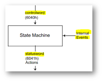 Figure 4. CiA402 state machine diagram
###Control word (object 0x6040)
Set by user, change the drive states.
Figure 4. CiA402 state machine diagram
###Control word (object 0x6040)
Set by user, change the drive states.
| Index | 0x6040 |
|---|---|
| Name | controlword |
| Object code | VAR |
| Data type | UINT |
| Access | RW |
| PDO mapping (pre-mapped) | Yes |
| Units | - |
| Range | - |
| Default value | 0 |
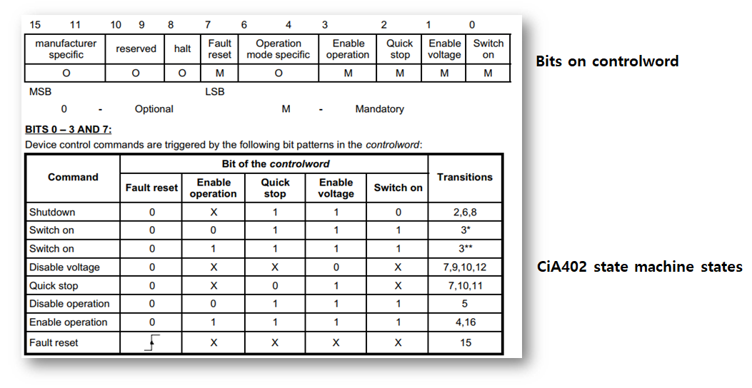 Figure 5. Detail information of Controlword
###Status word (object 0x6041)
Set by drive internally, indicate current state of drive.
Figure 5. Detail information of Controlword
###Status word (object 0x6041)
Set by drive internally, indicate current state of drive.
| Index | 0x6041 |
|---|---|
| Name | statusword |
| Object code | VAR |
| Data type | UINT |
| Access | RO |
| PDO mapping (pre-mapped) | Yes |
| Units | - |
| Range | - |
| Default value | - |
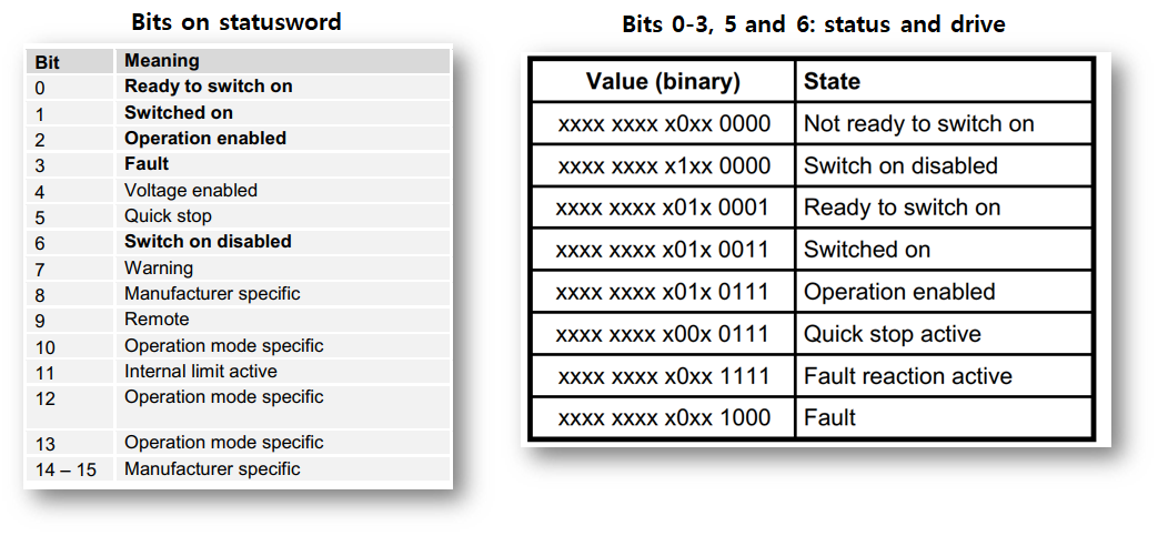 Figure 6. Detail information of Statusword
###Turn on/off servo via SDO
Since all objects can be accessed via SDO, including controlword and statusword.
User may turn CORE module on/off by writing suitable value for controlword via SDO.
According to CiA402 state machine, a proper SERVO-ON path will be:
Figure 6. Detail information of Statusword
###Turn on/off servo via SDO
Since all objects can be accessed via SDO, including controlword and statusword.
User may turn CORE module on/off by writing suitable value for controlword via SDO.
According to CiA402 state machine, a proper SERVO-ON path will be:
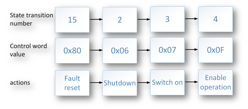 Figure 7. Servo ON path
A simplest way to turn off servo (SERVO-OFF) is to set controlword value of 0 (transition#9).
It is recommended that before turn module on, mode_of_operation should be set first.
###error_code (object 0x603F)
* Error_code: indicates actual error inside drive.
* Error code should be checked before starting operation and when Fault bit statusword appear.
Figure 7. Servo ON path
A simplest way to turn off servo (SERVO-OFF) is to set controlword value of 0 (transition#9).
It is recommended that before turn module on, mode_of_operation should be set first.
###error_code (object 0x603F)
* Error_code: indicates actual error inside drive.
* Error code should be checked before starting operation and when Fault bit statusword appear.
| Index | 0x603F |
|---|---|
| Name | error_code |
| Object code | VAR |
| Data type | UINT |
| Access | RO |
| PDO mapping (pre-mapped) | No |
| Units | - |
| Range | - |
| Default value | 0 |
| Code | Name | Description |
|---|---|---|
| 0x2310 | ERROR_CONTINUOUS_OVER_CURRENT | Hardware over-current, need reset before re-run |
| 0x3110 | ERROR_MAINS_OVER_VOLTAGE | Supplied 48V is too HIGH (> 63V) |
| 0x3120 | ERROR_MAINS_UNDER_VOLTAGE | Supplied 48V is too LOW (< 41V) |
| 0x3210 | ERROR_DC_LINK_OVER_VOLTAGE | Driver voltage (after enable) is too HIGH (> 62V) |
| 0x3220 | ERROR_DC_LINK_UNDER_VOLTAGE | Driver voltage (after enable) is too LOW (< 40V) |
| 0x7310 | ERROR_SPEED | Driver over speed, it is automatically recovery error |
| 0xFF10 | ERROR_ENCODER_BAT_LOW | Low battery of encoder -> replace battery |
| 0xFF11 | ERROR_ENCODER_ERR_BIT | There is error bit in encoder -> check bit count |
| 0xFF20 | ERROR_5V_SOURCE_OVER | Internal 5V is too HIGH (> 5.5V) |
| 0xFF21 | ERROR_5V_SOURCE_UNDER | Internal 5V is too LOW (< 4V) |
| 0xFF22 | ERROR_3_3V_SOURCE_OVER | Internal 3.3V is too HIGH (> 3.6V) |
| 0xFF23 | ERROR_3_3V_SOURCE_UNDER | Internal 3.3V is too LOW (< 3.0V) |
| 0xFF24 | ERROR_GATE_DRV_VOLTAGE_OVER | Internal Gate driver voltage is too HIGH (> 13V) |
| 0xFF25 | ERROR_GATE_DRV_VOLTAGE_UNDER | Internal Gate driver voltage is too LOW (< 9V) |
| 0xFF31 | ERROR_MOSFET_UL_THRU | Low side MOSFET, channel U is damaged |
| 0xFF32 | ERROR_MOSFET_VL_THRU | Low side MOSFET, channel V is damaged |
| 0xFF34 | ERROR_MOSFET_WL_THRU | Low side MOSFET, channel W is damaged |
| 0xFF39 | ERROR_MOSFET_UH_THRU | High side MOSFET, channel U is damaged |
| 0xFF3A | ERROR_MOSFET_VH_THRU | High side MOSFET, channel V is damaged |
| 0xFF3C | ERROR_MOSFET_WH_THRU | High side MOSFET, channel W is damaged |
| 0xFF3F | ERROR_MOSFET_UNKNOWN_THRU | Some MOSFET is damaged -> Over current |
 Figure 8. Torque control loop
| CORE module | Gear ratio | Torque constant (Nm/A) | Single-turn encoder resolution (counts) |
|---|---|---|---|
| CORE100 | 101 | 0.058 | 65536 |
| CORE200 | 121 | 0.087 | 65536 |
| CORE500 | 121 | 0.0884 | 65536 |
| CORE100 | ecat data | Motor current (A) | Motor torque (Nm) | CORE output torque (Nm) |
|---|---|---|---|---|
| Formula | a | I = a/96 | t = 0.058*I = 0.00060417*a | T = 101*t = 0.061004*a |
| Example | 96 | 1.0 | 0.058 | 5.858 |
| CORE200 | ecat data | Motor current (A) | Motor torque (Nm) | CORE output torque (Nm) |
|---|---|---|---|---|
| Formula | a | I = a/96 | t = 0.087*I = 0.00090625*a | T = 121*t = 0.10965625*a |
| Example | 96 | 1.0 | 0.087 | 10.527 |
| CORE500 | ecat data | Motor current (A) | Motor torque (Nm) | CORE output torque (Nm) |
|---|---|---|---|---|
| Formula | a | I = a/48 | t = 0.0884*I = 0.0018417*a | T = 121*t = 0.2228457*a |
| Example | 96 | 2.0 | 0.1768 | 21.393 |
| CORE100 | ecat data | Motor turns | CORE turns | CORE shaft angle (deg) |
|---|---|---|---|---|
| Formula | p | n = p/65536 | N = n/101= p/6619136 | A = 360*N = 360*p/6619136 |
| Example | 1241088 | 18.9375 | 0.1875 | 67.5 |
| CORE200 CORE500 |
ecat data | Motor turns | CORE turns | CORE shaft angle (deg) |
|---|---|---|---|---|
| Formula | p | n = p/65536 | N = n/121= p/7929856 | A = 360*N = 360*p/7929856 |
| Example | 1982464 | 30.25 | 0.25 | 90 |
| CORE100 | ecat data | Motor velocity (deg/s) | Motor speed (rpm) | CORE shaft velocity (deg/s) |
|---|---|---|---|---|
| Formula | y | v = 360*y/65536 | r = 60*y/65536=v/6 | V = v/101=360*y/6619136 |
| Example | 1311000 | 7201.538 | 1200.256 | 71.302 |
| CORE200 CORE500 |
ecat data | Motor velocity (deg/s) | Motor speed (rpm) | CORE shaft velocity (deg/s) |
|---|---|---|---|---|
| Formula | y | v = 360*y/65536 | r = 60*y/65536=v/6 | V = v/121=360*y/7929856 |
| Example | 1311000 | 7201.538 | 1200.256 | 59.517 |
digital_output:1 = 0xAAAA : release brake
digital_output:1 = other values: braked* Using brake release line: each ‘Brake lines’ connector (J2) on each driver has an ‘Brake release’ line, when this line is connected to GND, brake will be release regardless motor status
