Quick start: Maxon Motor example
This section gives you another example using commercial devices. To this end, this example uses a set of two COE (CANopen-over-EtherCAT) slaves and two EtherCAT IO modules. In particular, the two CoE slaves are MAXPOS servo drives from Maxon, which control two Maxon motors respectively. The both IO modules are connected to the encoder and inclinometer. The detailed information of those components is listed in the Table below.
| Device Type | Description | Amount |
|---|---|---|
| MAXPOS servo drive | MAXPOS 50/5 Positioning Controller | 2 |
| Maxon motor | Maxon motor 45 flat Ø42.8 mm, brushless, 70 Watt | 1 |
| Maxon motor | 60 flat Ø60 mm, brushless, 100 Watt | 1 |
| Beckhoff EL5101 | Incremental encoder interface | 1 |
| Autonics Encoder | Incremental encoder, Ø50mm Shaft type | 1 |
| Beckhoff EL3162 | 2-channel analog input terminals 0…10 V, single-ended, 16 bit | 1 |
| Posital Inclinometer | 2 axes, ±80 degree | 1 |
Components of EtherCAT slave system with Maxon motor
1) Connect EtherCAT Slaves to the Master. The EtherCAT network topology in this demonstration is described in the Figure

EtherCAT Topology for demonstration
2) Log in to the STEP/PC using PuTTY for scanning EtherCAT Slaves.
3) Execute the following command (on the PuTTY terminal) to check the state of every slave on the bus.
1 | |
As shown in the Figure, you can see a list of existing EtherCAT slaves including two MAXPOS driver, one Beckhoff EtherCAT coupler and two Beckhoff IO modules (EL5101 and EL3162).

4) Execute NRMKEcatService to export all slave information to the host PC.
1 2 3 | |
5) Execute NRMK EtherCAT Tool from NRMK Launcher in the host PC.
(Note that in this step, it is necessary to copy all ESI files, i.e., MAXPOS.xml, Beckhoff EL5xxx.xml and EL3xxx.xml, into the designated folder of EcatTool as follows.)
1 | |
6) Select the Searching System Information menu on EcatTool. Then, specify the TCP connection provided by NRMKEcatService of STEP/PC in the dialog, and click “connect” button as shown in the Figure. (Do not change the port number)

Searching for EtherCAT System Infromation on NRMK EtherCAT Tool
If NRMKEcatService is successfully connected, you will see the result in Figure, which shows a list of imported slaves and their information. Then, close the dialog and you are ready to configure the slaves.

7) Modify the attributes such as the slave icon, the vendor, the slave name, the alias and position of the slave as shown in Figure. Then, click Apply button to affect the current slaves.
(For automatic code generation, you must start with an alphabet character in setting the vendor and the slave name. They can only contain alphabets, numbers, or spaces.)

8) Map MAXPOS PDO Entries to the domain configuration. The point-by-point demonstrations are given below.
8.1) MAXPOS has four RxPDO mappings of index: 0x1600, 0x1601, 0x1602 and 0x1603 and four TxPDO mappings of index: 0x1A00, 0x1A01, 0x1A02 and 0x1A03. When you click any PDO mapping, the default PDO entries for the mapping will be listed in Entry Configuration panel.
8.2) Let’s start with RxPDO 0x1603 whose entries are shown in the Figure. The check button on the left of RxPDO 0x1603 means that this PDO will be chosen to map some or all of its PDO entries in the domain configuration. Therefore, If you want to map at least one PDO entry belonging to the PDO, it is mandatory to choose it first.
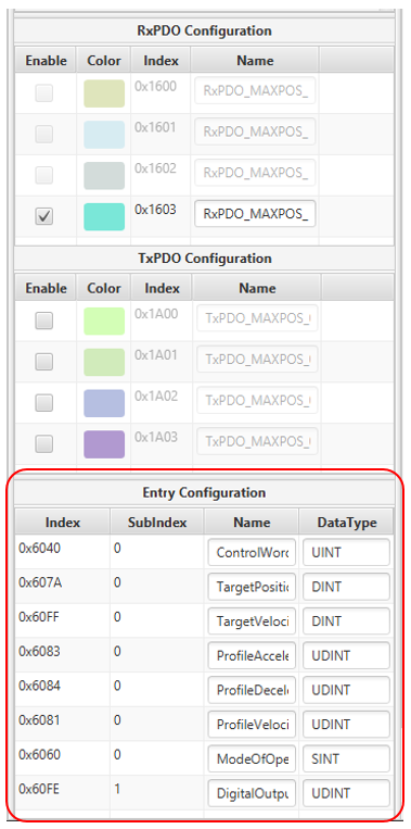
List of entries belonging to RxPDO 0x1603
8.3) Targetposition, Targetvelocity, and Targettorque are related to CST (Cyclic Synchronous Torque), CSP (Cyclic Synchronous Position) and CSV (Cyclic Synchronous Velocity) mode respectively. And each mode is executed by altering the operation mode, so it requires cyclic update of Target Position, Target Velocity, and Target Torque according to the chosen mode. However, in Entry Configuration panel, you can see only Target Position of index 0x607a and Target Velocity of index 0x60ff, which belong to the RxPDO mapping 0x1603.
8.4) Therefore, it is necessary to add Target Torque entry. There are two alternatives: One may search for another RxPDO mapping containing the entry and select it additionally. The other may remap the default entries for the current PDO mapping. This example will choose the second method because it needs to add only one entry. To add Target Torque to this PDO mapping, right-click on it and choose Setting menu as shown in the Figure.

Modifying RxPDO mapping 0x1603
8.5) Then, Add Entry dialog will appear as shown in Figure. Please choose the TargetTorque (of index 0x6071) entry from the Available Entries list and click >> button to add it to the list of entries.
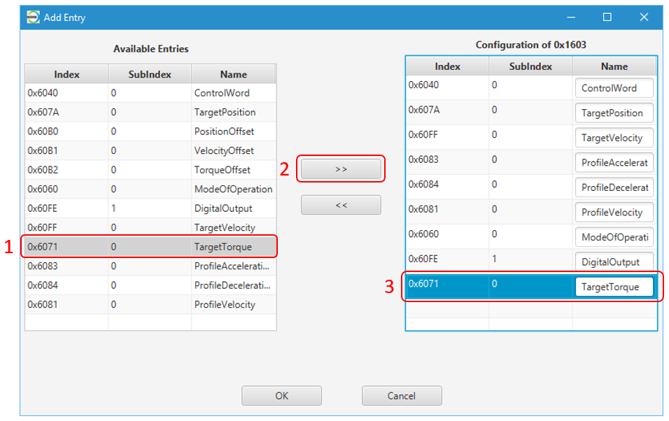
Adding Target Torque object to RxPDO 0x1603
8.6) Now, RxPDO 0x1603 has nine entries, but the maximum number of this PDO is only eight (as it can be guessed from the number of the default entries). Thus, you have to remove one unnecessary entry from the default PDO entries. As an example, you can remove DigitalOutput entry by selecting it and click << button as instructed in the Figure. Finally, click “OK” button to confirm the modification.

Removing DigitalOutput from RxPDO 0x1603
8.7) The next step is importing some or all PDO entries into a domain[^10].
Select all necessary entries you want to import, right-click and choose Add to Domain menu. Then all selected entries will be imported automatically into RxDomain (Sending from the master) as shown in Figure.

Importing RxPDO entries into RxDomain
8.8) Finally, you also need to import the TxPDO entries. For this tutorial, select TxPDO 0x1A01 because it contains all important entries such as actual position, actual velocity, actual torque, and so on. Then, add the entries of TxPDO 0x1A01 to TxDomain (Receiving by the master) as shown in Figure.

Importing TxPDO entries into Receiving domain
9) Map Beckhoff EL5101 PDO entries to the domain configuration. The pointy-by-point demonstrations are given below.
9.1) Beckhoff EL5101 consists of one RxPDO 0x1600 and one TxPDO 0x1A00. However, there is one thing you have to notice that both the RxPDO 0x1600 and the TxPDO 0x1A00 contain two entries that share the same name “Value” (having different index) as shown in Figure. This will cause some errors in the automatically generated code by EcatTool, meaning that it is necessary to change the name of one entry.
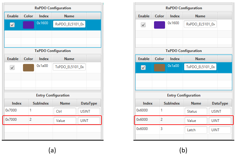
Beckhoff EL5101: RxPDO 0x1600 (a) and TxPDO 0x1A00 (b)
9.2) To solve the issue, change the name of entry so that each name is unique by directly modifying the text fields in “Name” column. The names of two entries are replaced with SendValue and GetValue like the Figure.

Beckhoff EL5101 – (a) RxPDO 0x1600 and (b) TxPDO 0x1A00 after modification
9.3) The final step is importing entries from RxPDO 0x1600 and TxPDO 0x1A00 into domains, which can be done in the same way as MAXPOS in the previous subsection.
10) Map Beckhoff EL3162 PDO entries to the domain configuration. The pointy-by-point demonstrations are given below.
10.1) The case of EL3162 is much easier than of MAXPOS and EL5101. Beckhoff EL3162 provides three TxPDOs: 0x1A00, 0x1A01 and 0x1A10. This example chooses the TxPDO 0x1A10, which contains two objects of inclinometer (Value1 and Value2 as in the Figure. Every step is similar to the previous slaves.
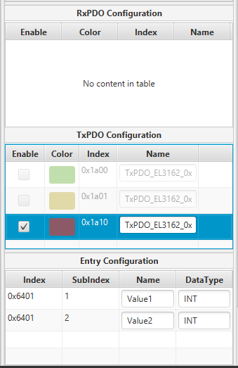
Beckhoff EL3162 – TxPDO 0x1A10
10.2) After finishing configuration of MAXPOS, EL5101 and EL3162, your RxDomain and TxDomain should look like the ones in the Figure Then, you can move forward to the next section.
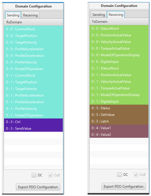
The final result of RxDomain and TxDomain
11) Set Distributed Clock (DC) configuration.
11.1) DC is one of EtherCAT features, which enables synchronized communication across slaves based on one reference clock (which is usually the first slave supporting DC mode). However, some slaves do not support DC mode. In the current demonstration system, MAXPOS servo drives provide complete DC functions, but Beckhoff DIO slaves do not. This section describeds how to configure DC mode for the EtherCAT system interface.
11.2) Please click on the DC check box at the bottom of Domain Configuration panel to enable DC mode. Then, Distributed Clock Setting dialog appears to set DC mode for each EtherCAT slave as shown in the Figure.
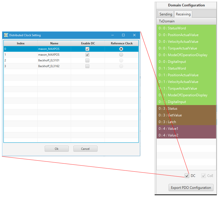
Distributed Clock Configuration
11.3) On the Distributed Clock Setting dialog, please enable DC on MAXPOS only and leave two Beckhoff IO modules disabled1. Moreover, choose one of two MAXPOS as Reference Clock for DC operation. Finally, click OK button to finish configuration.
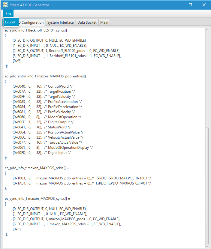
12) Generate realtime code for the current system. As shown in Figure, click Export PDO Configuration button to start generating C++ code for realtime control. System Setting dialog appears to specify your C++ project. Specify System Name, Control Period, and Platform PC option for STEP/PC or STEP/HPC (all based on Intel x86 architecture), or Platform IMX for STEP/iMX or STEP/BBB (all based on ARM architecture), and click OK button.

Setting C++ Project on Eclipse
13) Review the generated C++ code before exporting it to source files. Then, click the File menu and select Export to generate the source code and the project as shown in the Figure.
14) In the Save As dialog, create a new folder (e.g. EcatDemonstration) in the workspace of NRMKPlatform. For STEP/PC, the directory is as follows:
1 | |
Then, click Save to generate all project codes.
15) After executing Eclipse, click File and Import as shown in the Figure.
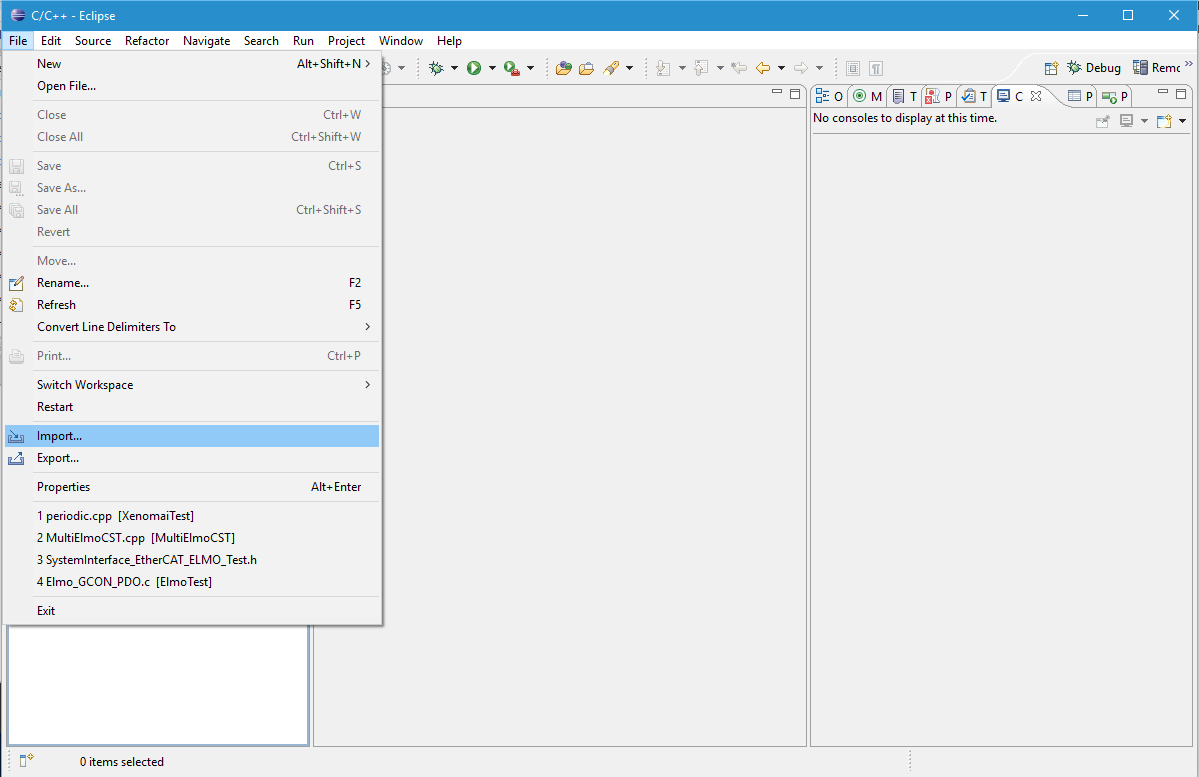
16) In the Import dialog, select Existing Projects into Workspace option as shown in the Figure.
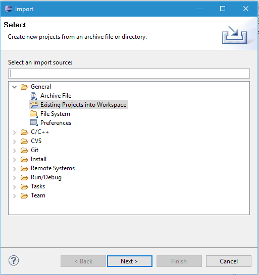
Selecting Existing Projects into Workspace
17) Specify the directory where you put the source files in the previous section, in Select root directory field. In this example, it is:
1 | |
If the directory is correctly selected, your EtherCAT project will be shown in Projects list as shown in the Figure.
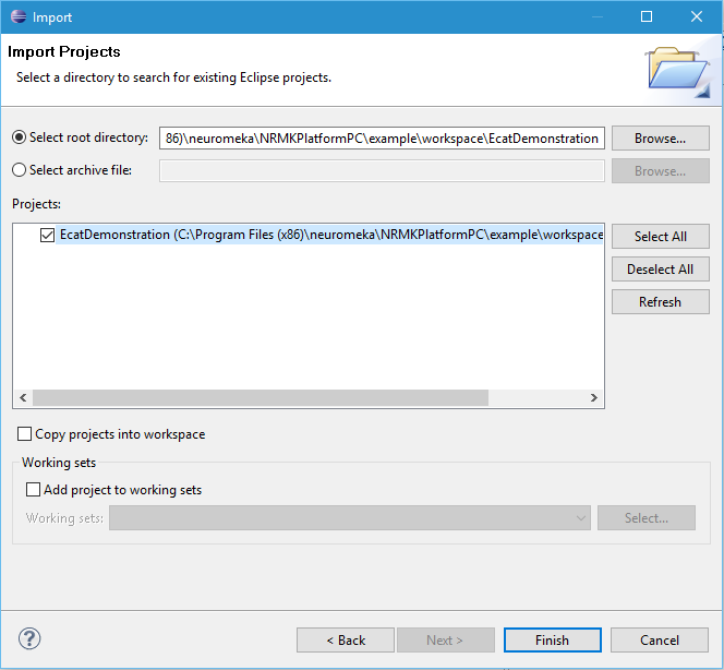
Specifying EtherCAT Project Directory
18) Click Finish button, and you will have your project listed in Eclipse’s Project Explorer. See the Figure.
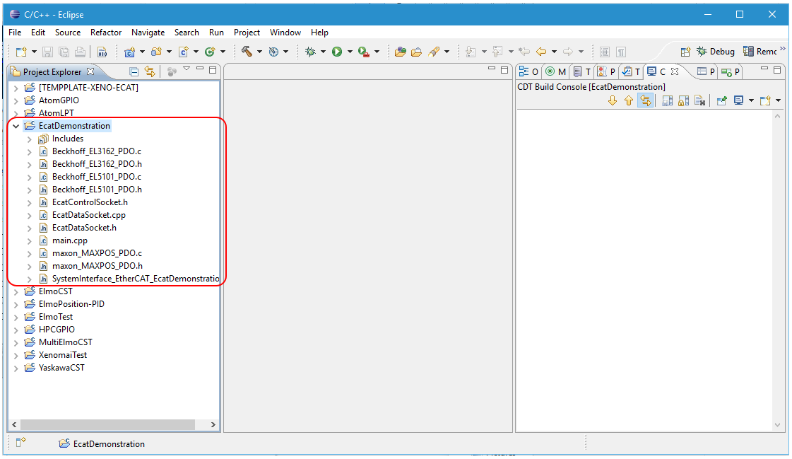
EtherCAT Project listed in Eclipse's Project Explorer
19) Set Build Configuration to Release as described in the Figure in order for Eclipse to generate release version of the EtherCAT application.
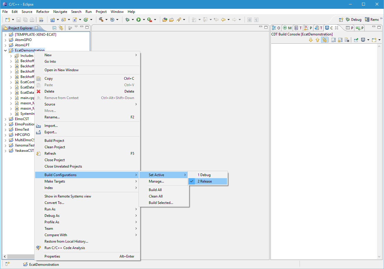
Setting Build Configuration to Release
20) To compile the EtherCAT project, click Project and Build Project menu as shown in Figure. When you see the message shown below in Console window of Eclipse, your project has been built successfully.
1 2 | |
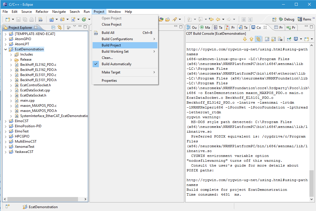
Compiling EtherCAT Project in Eclipse
-
In ESI xml file, the attribute regarding DC mode support is prescribed. But some slaves have possibly incorrect specification. The best way is to consult their accompanied documents. Trial to enable DC mode for slaves not supporting DC mode results in failure to EtherCAT system interface in running the application. ↩
