Modbus TCP
The Indy API supports Modbus TCP, one of the industrial fieldbus communication protocols. Modbus TCP is primarily used to receive robot data from external devices (PC, PLC, peripherals, etc.) and to issue commands to the robot.
Typically, robot configuration, teaching (teaching), and robot programming tasks are performed through the Neuromeka teaching pendant app Conty. Commands to execute/stop registered robot programs can be performed from external devices using not only Conty but also IndyDCP or Modbus TCP.
Modbus TCP uses dedicated communication and communicates through the TCP/IP network protocol. To use the TCP/IP protocol, the control box must be connected to the external device using Modbus TCP via Ethernet. The controller of the control box driving the robot acts as a slave (server), and up to 32 masters (clients) can be connected. The table below is the connection information for the Modbus TCP server.
| Item | Details |
|---|---|
| IP Address | Ethernet IP address of the robot |
| Port Number | 502 |
| Maximum Number of Connections | 32 |
| Maximum Communication Cycle | 100Hz (10ms) |
Modbus TCP Robot Programming Method through Conty
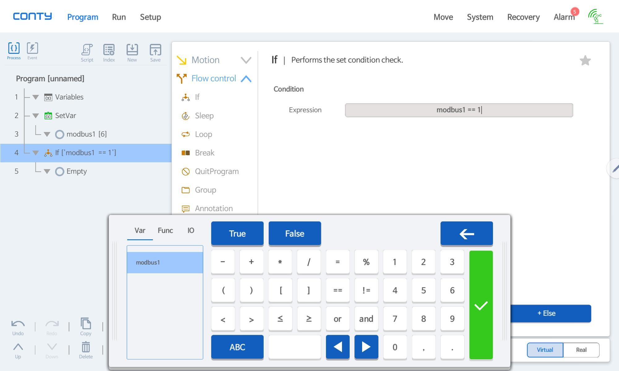
In Conty, Modbus variables can be defined through the Variables command, and values can be assigned to the variables through the SetVar command. Additionally, logic based on defined Modbus values can be implemented through 'expression' input in condition commands such as If.
Below are examples of SetVar and conditional input in Conty.

Memory Address Information
Modbus TCP supports coils (bit-wise addresses) and registers (16-bit addresses), but the Indy API primarily uses registers.
Registers 0 ~ 999 are user areas, where users can freely assign necessary memory addresses as variables and use them without regard to Read and Write.
In Conty programs, user area addresses can be freely accessed through Modbus variables as shown in the picture below.

Registers 1000~3999 are reserved areas, used for controlling the robot or reading robot data.
| Address | Features |
|---|---|
| 0 - 999 | User area (freely usable) |
| 1000-3999 | Reserved area (restricted reading/writing) |
Information by Reserved Area Address
The tables below represent data information according to memory addresses in the reserved area. Each address has a different purpose (Read/Write), and although all are basically usable as registers, some data sizes are 8 bits and can also be accessed as coils. Coil accessibility is indicated.
In most cases, the assigned status variables are 1 (true) and 0 (false), and variables that can only be accessed as registers have 16-bit integer values (for example, the program index at address 1040 is 1-10).
Receiving Robot Status (Robot Status)
Robot status uses addresses 1000-1099.
| Address | Read/Write | Description | Coil | Comment |
|---|---|---|---|---|
| 1010 | R | isRobotControllerRunning | O | Robot controller running |
| 1011 | R | isRobotReady | O | Robot is ready to move (all Servos On, etc.) |
| 1012 | R | isErrorState | O | Robot is in error state |
| 1013 | R | isCollided | O | Robot has detected a collision |
| 1014 | R | isEmergencyStopped | O | Emergency stop state |
| 1015 | R | isBusy | O | Robot is currently moving |
| 1016 | R | isMoveFinished | O | Robot has completed movement command and reached the target successfully |
| 1017 | R | isHome | O | Robot is in home position |
| 1018 | R | isZero | O | Robot is in zero position |
| 1019 | R | isInResetting | O | Robot is resetting |
| 1040 | R | Registered Default Program Index | X | Currently registered default Conty program number |
| 1080 | R | isDirectTeachingMode | O | Direct teaching mode state |
| 1081 | R | isTeachingMode | O | Teaching state using JOG button, etc. |
| 1082 | R | isContyConnected | O | Conty connection state |
| 1083 | R | isProgramRunning | O | Program is running (including paused) |
| 1084 | R | isProgramPaused | O | Program is paused |
Robot Control Commands and Program Execution
To send commands for controlling the robot, you can write a value of 1 to addresses 1100~1299. The Modbus server uses a rising bit to recognize commands. That means it only recognizes and executes a command when the state changes from 0 to 1.
If you wish to reissue a command assigned to the same address, you must change the value from 1 to 0 and then back to 1 to create a bit rising. Since the maximum communication cycle of Modbus TCP is 100Hz, you must wait 10ms before sending the command.
If the command results in moving the robot, it will be ignored if the robot is already moving or if a program is currently running. Also, if multiple commands are issued simultaneously, the command with the highest priority will be executed, and the others may be ignored, so care must be taken when issuing commands.
Program Execution Commands
Commands 1100~1104 are related to executing programs written in Conty.
Commands 1110~1119 are related to the default programs stored in Conty. You can register one of the default programs 1~10 stored in Conty on the robot via Modbus TCP or Conty. After registering a default program using commands 1110~1119, you can execute the registered default program with command 1100.
| Address | Read/Write | Description | Coil | Comment |
|---|---|---|---|---|
| 1100 | W | Start Registered Default Program | O | Execute the currently registered default Conty program |
| 1101 | W | Start Program | O | Execute the currently loaded program |
| 1102 | W | Stop Program | O | Stop the currently running program |
| 1103 | W | Pause Program | O | Pause the currently running program |
| 1104 | W | Resume Program | O | Resume the currently paused program |
| 1110~1119 | W | Register Default Program 1~10 | O | Register one of the stored default programs 1~10 on robot |
Basic Robot Control Commands
Commands 1160~1165 are basic commands for robot control, such as reset, force reset, stop motion, emergency stop, move to home position, and move to zero position.
The reset command (1160) can be used for general error situations. It allows you to reset errors like speed exceedance or collision detection and give commands to the robot again. During such a reset, the status value 1019 becomes 1, indicating the robot is in resetting mode.
The stop motion command (1162) stops the currently moving robot and program.
Commands 1164 and 1165 are for moving the robot to the home or zero position, respectively. These commands only operate when the robot is not moving or a program is not running.
| Address | Read/Write | Description | Coil | Comment |
|---|---|---|---|---|
| 1160 | W | Reset | O | Reset the robot (e.g., error reset) |
| 1162 | W | Stop Motion | O | Stop the current motion |
| 1163 | W | Emergency Stop | O | Emergency stop |
| 1164 | W | Move to Home | O | Move to home position |
| 1165 | W | Move to Zero | O | Move to zero position |
| 1170 | W | Switch To Direct Teaching Mode | O | Change to direct teaching mode |
| 1171 | W | Finish Direct Teaching Mode | O | End direct teaching mode |
Receiving Robot Data
Robot coordinates are divided into joint space coordinates and task space coordinates. Joint space coordinates represent the position using the angles of each robot joint, while task space coordinates represent the position in 3D space based on the robot's base, using the tool center position (TCP).
Addresses 1300-1305 represent the joint space coordinates, corresponding to the angles of robot axes 1~6. For a 7-axis robot, it would be 1300~1306 for axes 1~7. The unit is mrad (1/1000th of a radian), represented as a signed 16-bit integer. Addresses 1310-1315 represent the current angular velocity for axes 1~6, and 1380-1385 represent the current force (torque) for axes 1~6.
Addresses 1600-1605 represent task space coordinates, showing xyzuvw values. xyz represents the distance from the robot base to the TCP
along the xyz coordinate axes, while uvw represents the rotation direction of the tool endpoint, expressed in Euler Angles with the rotation order of w > v > u (rZ > rY > rX). The unit for xyz is 1/10mm (1/10000th of a meter), and for uvw, it is mrad. Addresses 1610-1615 represent the current speed of movement/rotation in task space coordinates.
For users requiring more detailed units, 32-bit float data is also supported. Addresses 1400-1411, 1700-1711, etc., use two consecutive addresses (e.g., 1400-1401) to represent data in 32-bit float format. These values cannot be accessed through coils.
| Joint(as WORD) | ||||
|---|---|---|---|---|
| Address | Read/Write | Description | Data Range | Comment |
| 1300 | R | Base joint angle (in mrad) | 16bit | Angle of Axis 1 (the axis closest to the robot base, similarly hereinafter) |
| 1301 | R | Shoulder joint angle (in mrad) | 16bit | Angle of Axis 2 |
| 1302 | R | Elbow joint angle (in mrad) | 16bit | Angle of Axis 3 |
| 1303 | R | Wrist1 joint angle (in mrad) | 16bit | Angle of Axis 4 |
| 1304 | R | Wrist2 joint angle (in mrad) | 16bit | Angle of Axis 5 |
| 1305 | R | Wrist3 joint angle (in mrad) | 16bit | Angle of Axis 6 |
| 1306 | R | Wrist4 joint angle (in mrad) | 16bit | Angle of Axis 7 |
| 1310 | R | Base joint angle velocity (in mrad/s) | 16bit | Velocity of Axis 1 |
| 1311 | R | Shoulder joint angle velocity (in mrad/s) | 16bit | Velocity of Axis 2 |
| 1312 | R | Elbow joint angle velocity (in mrad/s) | 16bit | Velocity of Axis 3 |
| 1313 | R | Wrist1 joint angle velocity (in mrad/s) | 16bit | Velocity of Axis 4 |
| 1314 | R | Wrist2 joint angle velocity (in mrad/s) | 16bit | Velocity of Axis 5 |
| 1315 | R | Wrist3 joint angle velocity (in mrad/s) | 16bit | Velocity of Axis 6 |
| 1316 | R | Wrist4 joint angle velocity (in mrad/s) | 16bit | Velocity of Axis 7 |
| 1350-1356 | R | Joint torque sensor values(in Nm) | 16bit | Torque sensor values of Axis 1-7 |
| 1360-1366 | R | Joint torque sensor raw_1 values (in Nm) | 16bit | Torque sensor 1 values of Axis 1-7 |
| 1370-1376 | R | Joint torque sensor raw_2 values (in Nm) | 16bit | Torque sensor 2 values Axis 1-7 |
| 1380 | R | Base joint torque (in Nm) | 16bit | Torque of Axis 1 |
| 1381 | R | Shoulder joint torque (in Nm) | 16bit | Torque of Axis 2 |
| 1382 | R | Elbow joint torque (in Nm) | 16bit | Torque of Axis 3 |
| 1383 | R | Wrist1 joint torque (in Nm) | 16bit | Torque of Axis 4 |
| 1384 | R | Wrist2 joint torque (in Nm) | 16bit | Torque of Axis 5 |
| 1385 | R | Wrist3 joint torque (in Nm) | 16bit | Torque of Axis 6 |
| 1386 | R | Wrist4 joint torque (in Nm) | 16bit | Torque of Axis 7 |
| Joint(as Float) | ||||
|---|---|---|---|---|
| Address | Read/Write | Description | Data Range | Comment |
| 1400-1401 | R | Base joint angle (in rad) | 32bit | Angle of Axis 1 |
| 1402-1403 | R | Shoulder joint angle (in rad) | 32bit | Angle of Axis 2 |
| 1404-1405 | R | Elbow joint angle (in rad) | 32bit | Angle of Axis 3 |
| 1406-1407 | R | Wrist1 joint angle (in rad) | 32bit | Angle of Axis 4 |
| 1408-1409 | R | Wrist2 joint angle (in rad) | 32bit | Angle of Axis 5 |
| 1410-1411 | R | Wrist3 joint angle (in rad) | 32bit | Angle of Axis 6 |
| 1412-1413 | R | Wrist4 joint angle (in rad) | 32bit | Angle of Axis 7 |
| 1420-1421 | R | Base joint angle velocity (in rad/s) | 32bit | Velocity of Axis 1 |
| 1422-1423 | R | Shoulder joint angle velocity (in rad/s) | 32bit | Velocity of Axis 2 |
| 1424-1425 | R | Elbow joint angle velocity (in rad/s) | 32bit | Velocity of Axis 3 |
| 1426-1427 | R | Wrist1 joint angle velocity (in rad/s) | 32bit | Velocity of Axis 4 |
| 1428-1429 | R | Wrist2 joint angle velocity (in rad/s) | 32bit | Velocity of Axis 5 |
| 1430-1421 | R | Wrist3 joint angle velocity (in rad/s) | 32bit | Velocity of Axis 6 |
| 1432-1433 | R | Wrist4 joint angle velocity (in rad/s) | 32bit | Velocity of Axis 7 |
| 1500-1513 | R | Joint torque sensor values(in Nm) | 32bit | Torque sensor values of Axis 1-7 |
| 1520-1533 | R | Joint torque sensor raw_1 values (in Nm) | 32bit | Torque sensor 1 values of Axis 1-7 |
| 1540-1553 | R | Joint torque sensor raw_2 values (in Nm) | 32bit | Torque sensor 2 values Axis 1-7 |
| 1560-1561 | R | Base joint torque (in Nm) | 32bit | Torque of Axis 1 |
| 1562-1563 | R | Shoulder joint torque (in Nm) | 32bit | Torque of Axis 2 |
| 1564-1565 | R | Elbow joint torque (in Nm) | 32bit | Torque of Axis 3 |
| 1566-1567 | R | Wrist1 joint torque (in Nm) | 32bit | Torque of Axis 4 |
| 1568-1569 | R | Wrist2 joint torque (in Nm) | 32bit | Torque of Axis 5 |
| 1570-1571 | R | Wrist3 joint torque (in Nm) | 32bit | Torque of Axis 6 |
| 1572-1573 | R | Wrist4 joint torque (in Nm) | 32bit | Torque of Axis 7 |
| Task(as WORD) | ||||
|---|---|---|---|---|
| Address | Read/Write | Description | Data Range | |
| 1600 | R | TCP-x in 1/10 of mm (in base frame) | 16bit | |
| 1601 | R | TCP-y in 1/10 of mm (in base frame) | 16bit | |
| 1602 | R | TCP-z in 1/10 of mm (in base frame) | 16bit | |
| 1603 | R | TCP-rx in mrad (in base frame) | 16bit | |
| 1604 | R | TCP-ry in mrad (in base frame) | 16bit | |
| 1605 | R | TCP-rz in mrad (in base frame) | 16bit | |
| 1610 | R | TCP-x velocity in 1/10 of mm/s(in base frame) | 16bit | |
| 1611 | R | TCP-y velocity in 1/10 of mm/s(in base frame) | 16bit | |
| 1612 | R | TCP-z velocity in 1/10 of mm/s(in base frame) | 16bit | |
| 1613 | R | TCP-rx velocity in mrad/s (in base frame) | 16bit | |
| 1614 | R | TCP-ry velocity in mrad/s (in base frame) | 16bit | |
| 1615 | R | TCP-rz velocity in mrad/s (in base frame) | 16bit | |
| Task(as Float) | ||||
|---|---|---|---|---|
| Address | Read/Write | Description | Data Range | 1700-1701 | R | TCP-x in m (in base frame) | 32bit |
| 1702-1703 | R | TCP-y in m (in base frame) | 32bit | |
| 1704-1705 | R | TCP-z in m (in base frame) | 32bit | |
| 1706-1707 | R | TCP-rx in rad (in base frame) | 32bit | |
| 1708-1709 | R | TCP-ry in rad (in base frame) | 32bit | |
| 1710-1711 | R | TCP-rz in rad (in base frame) | 32bit | |
| 1720-1721 | R | TCP-x velocity in m/s (in base frame) | 32bit | |
| 1722-1723 | R | TCP-y velocity in m/s (in base frame) | 32bit | |
| 1724-1725 | R | TCP-z velocity in m/s (in base frame) | 32bit | |
| 1726-1727 | R | TCP-rx velocity in rad/s (in base frame) | 32bit | |
| 1728-1729 | R | TCP-ry velocity in rad/s (in base frame) | 32bit | |
| 1730-1731 | R | TCP-rz velocity in rad/s (in base frame) | 32bit | |
Robot Error Data
When the robot is in an emergency or error state, the cause can be identified through the values of registers 2900~2906. Register 2900 represents the event code, and registers 2901~2906 contain data related to this event code, with different meanings depending on the event.
| Address | Read/Write | Description | Data Range | Comment |
|---|---|---|---|---|
| 2900 | R | Emergency Event Code (Integer) | 16bit | Emergency situation event code |
| 2901 | R | Emergency Event Data Arg1 (16bit Signed Integer) | 16bit | Emergency event data 1 |
| 2902 | R | Emergency Event Data Arg2 (16bit Signed Integer) | 16bit | Emergency event data 2 |
| 2903 | R | Emergency Event Data Arg3 (16bit Signed Integer) | 16bit | Emergency event data 3 |
| 2904 | R | Emergency Event Data Arg4 (Floating Point (x1000)) | 16bit | Emergency event data 4 |
| 2905 | R | Emergency Event Data Arg5 (Floating Point (x1000)) | 16bit | Emergency event data 5 |
| 2906 | R | Emergency Event Data Arg6 (Floating Point (x1000)) | 16bit | Emergency event data 6 |
Basic Input/Output Control
Digital/Analog Input/Output (DIO, AIO) can be controlled via Modbus TCP. DI 00~31 are allocated to registers 3000~3031, and AI 00~03 are allocated to registers 3200-3203, allowing you to read the values of each register to check the DI, AI values.
Note
There are 32 DIOs and 4 AIOs, respectively, but unused numbers are also included for future expandability.
DO and AO can also be controlled via Conty for robot programming, Indy API, etc., in addition to Modbus TCP. When controlled simultaneously, conflicts may arise, and to avoid such situations, DO and AO control via Modbus is disabled by default.
The default value for DO is 2 (None), meaning that the Modbus register mapped to DO is not used. If you wish to control DO via Modbus TCP, input HIGH(1) or LOW(0) values into the respective register. When controlling DO via register input, it takes precedence over other control methods (Conty or IndyAPI).
Similarly, AO control via Modbus takes precedence. AO control values range from 0~10000, where 0 represents 0V, and 10000 represents 10V. All values other than these imply None (default None value is 50000), meaning AO is not controlled via Modbus TCP.
| Address | Read/Write | Description | Data Range | Comment |
|---|---|---|---|---|
| 3000-3031 | R | SmartDI_00~31 | 0~1 | HIGH(1), LOW(0) |
| 3100-3131 | W | SmartDO_00~31 | 0~1 | HIGH(1), LOW(0), NONE(other) |
| 3200-3203 | R | SmartAI_00~03 | 16bit | 0~10V to 0~10000 |
| 3220-3223 | W | SmartAO_00-03 | 16bit | 0~10V to 0~10000, NONE(other) |
Additional Input/Output Control
Registers 3400~3437 can be used to read FTSensor data. It supports both the CB and robot CAN ports (the robot CAN port exists only on IndyRP, IndyRP2, Indy7), with both Raw and Transformed data available. The order is XYZUVW, with the unit for XYZ being [N] and for UVW being [Nm].
| Address | Read/Write | Description | Data Range | Comment |
|---|---|---|---|---|
| 3400-3405 | R | FTSensor Data from Robot CAN (Raw)(16bit Signed Integer) | 16bit | FTSensor Raw from robot Tool CAN port |
| 3406-3417 | R | FTSensor Data from Robot CAN (Transformed)(32bit Signed Integer) | 32bit | FTSensor Transformed Data from robot Tool CAN port ([N], [Nm]) |
| 3420-3425 | R | FTSensor Data from CB CAN (Raw)(16bit Signed Integer) | 16bit | Raw FTSensor values from CB's CAN port |
| 3426-3437 | R | FTSensor Data from CB CAN (Transformed)(32bit Floating Integer) | 32bit | Transformed FTSensor Data from CB's CAN port ([N], [Nm]) |
