Object Inspection Example
Graph Wizard is a function that can easily compose a graph based on guidelines without the user completely understanding the graph module. Click Wizard on the Detection tab, select suitable items for the current environment from the various selections in order, then you can finish the graph of the object to be detected. This tutorial explains Object Inspection Practice, one of the typical applications provided from IndyEye, using the Wizard.
Object Inspection Practice consists of two parts.
- Create a detection graph that detects the color of the sticker attached to the product with the Graph Wizard function.
- Manually create a graph that checks the existence of a hole on the object.
You can follow the same process if you have a product similar to the example used in this tutorial.
Color and Circularity Inspection
First, place an object on the workspace and click the Refresh button on the camera image at the left side of the application to automatically adjust the exposure. Then, click the Wizard button on the Detection tab and start composing the graph by selecting items in the following order:
- Clear Graph ⇒ Create a new image recognition algorithm pipeline ⇒ Camera frame ⇒ Sharpen ⇒ (Next step) ⇒ Detect specific color ⇒ Fill inside of detected mask ⇒ (Next step) ⇒ Check circularity ⇒ (Next step) ⇒ Do not estimate orientation ⇒ Fit the object position on the work plane? (No)

Graph Module Adding Completed
After you finish adding the graph modules, you can see the MaskHSV, Fill, and Circularity modules has been added in the graph. MaskHSV and Circularity are used for distinguishing objects by examining sticker color and shape, and Fill is used for compensating sticker material. Click MaskHSV to record sticker color and click SET in the detailed settings. SET is a function that saves values of specific areas of the camera image by touching it. Therefore, touch the SET button, and touch the sticker area in the camera image to save color values.
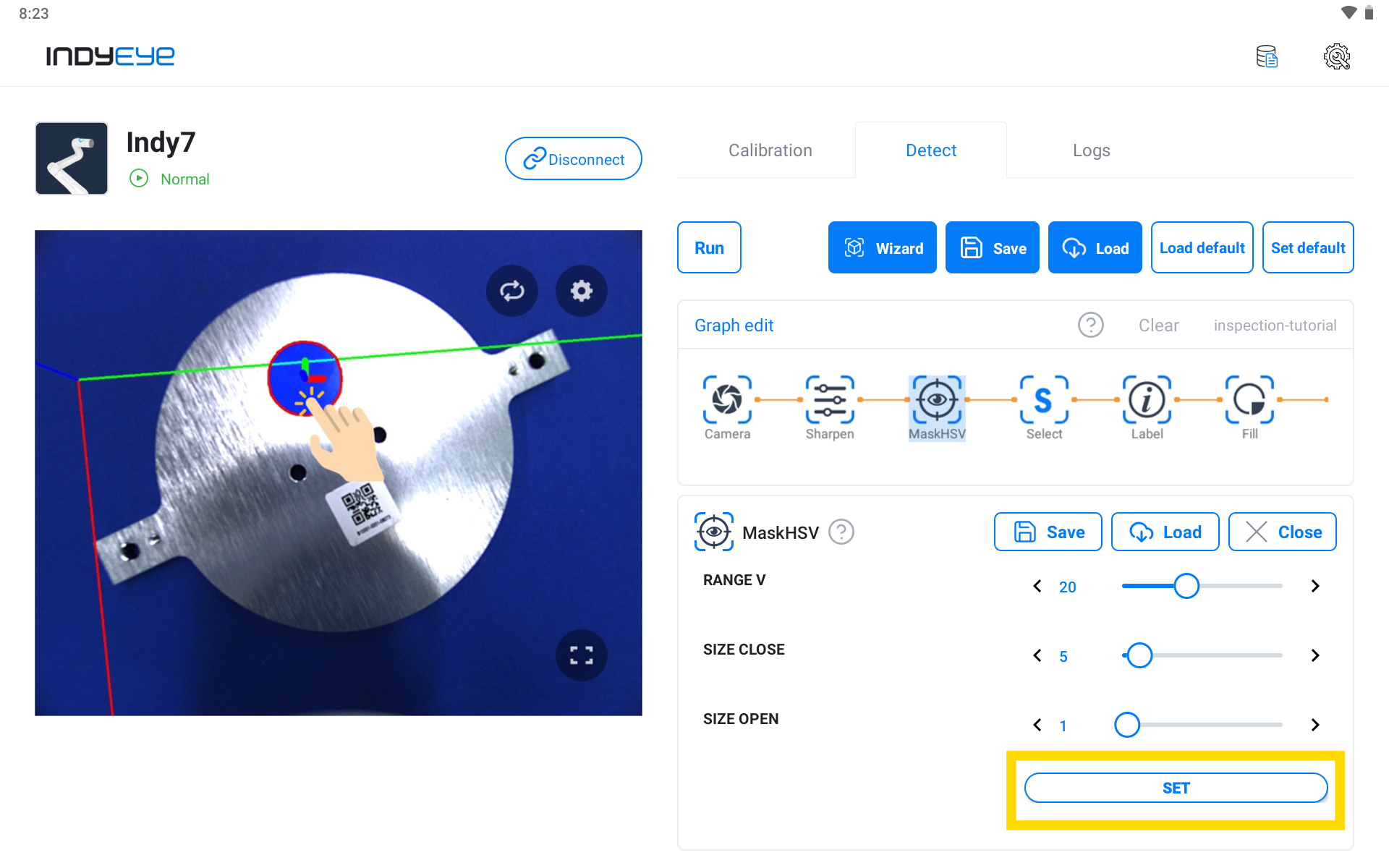
MaskHSV Module Settings
Next, click the Label module to give the detected sticker a name. Write in the NAME field of the detailed settings to give it a name.
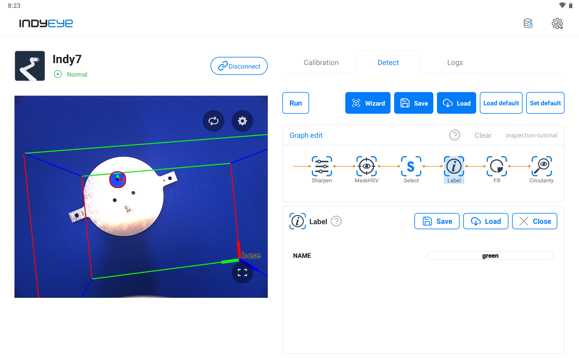
Label Module Settings
Now, proceed to the Circularity module setup to examine the shape of the sticker by checking the circularity of the detected area. Adjust the CUT value from the detailed settings, and if the object’s value is higher than that, it is detected as a circle. Like the picture below, a circle sticker is detected by adjusting the value.

Circularity Module Settings
After completing the prior setup, click the Execute button and you can see the circle sticker normally detected with the pass sign marked.
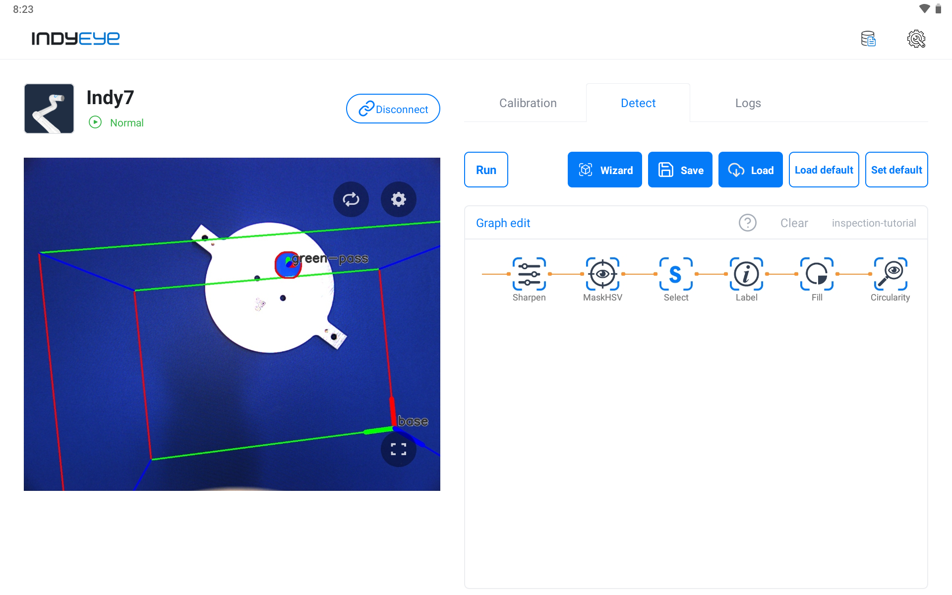
Color and Circularity Inspection (pass)
If the sticker isn’t round, the fail sign is marked like below.
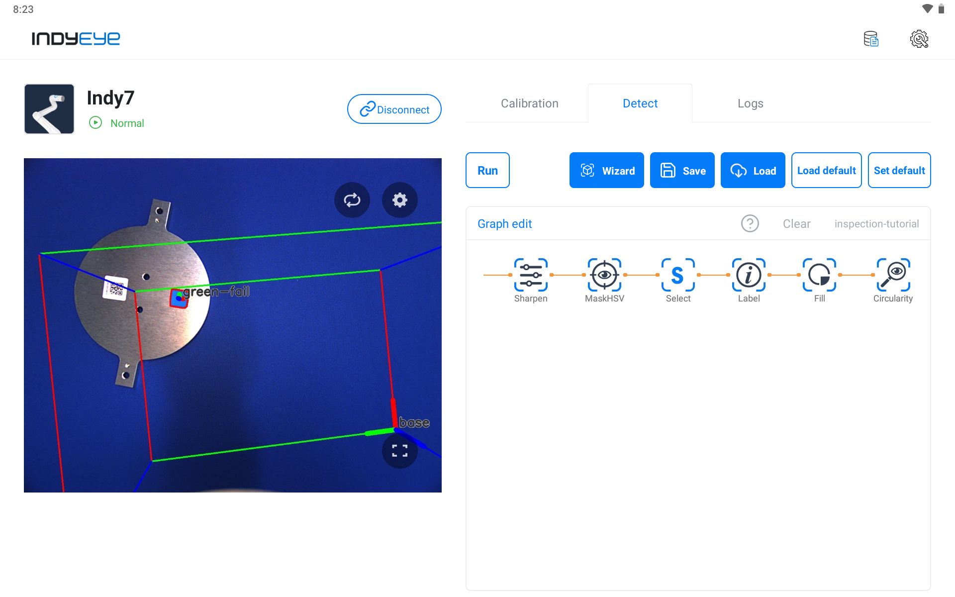
Color and Circularity Inspection (fail)
Hole Inspection
Following the prior inspection graph, next we explain the process of adding graph modules and proceeding with the hole inspection. Save graphs used on color and circularity inspection first. Then click Empty to reset the graph. Reset graph to add graph modules used for the hole inspection and click Modify Graph to make the module consist of that as pictured below.
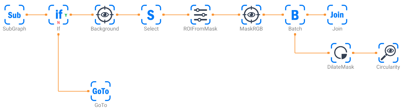
Additional Graph Composition
While the graph modification is active, you can compose a graph by dragging or clicking each module from the module list panel on the left side of the screen.
After composing a graph, click SubGraph and select the color and circularity inspection graph saved in advance from NAME.
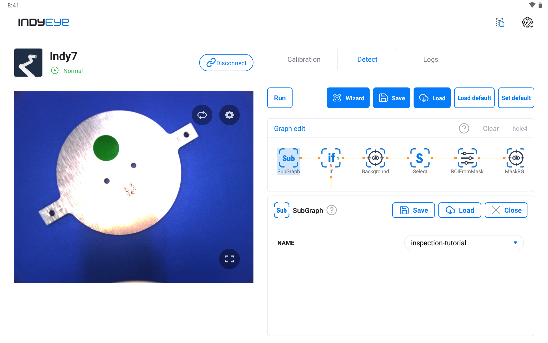
SubGraph Module Settings
The If module on the side works as a branch that enables further progress if color and circularity are detected as normal. Enable hole inspection if the sticker inspection is passed by consisting of the detailed settings below.
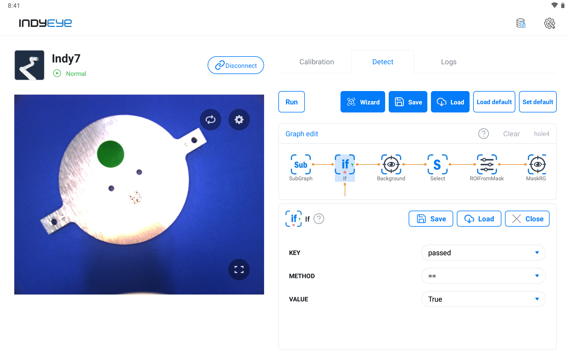
If Module Settings
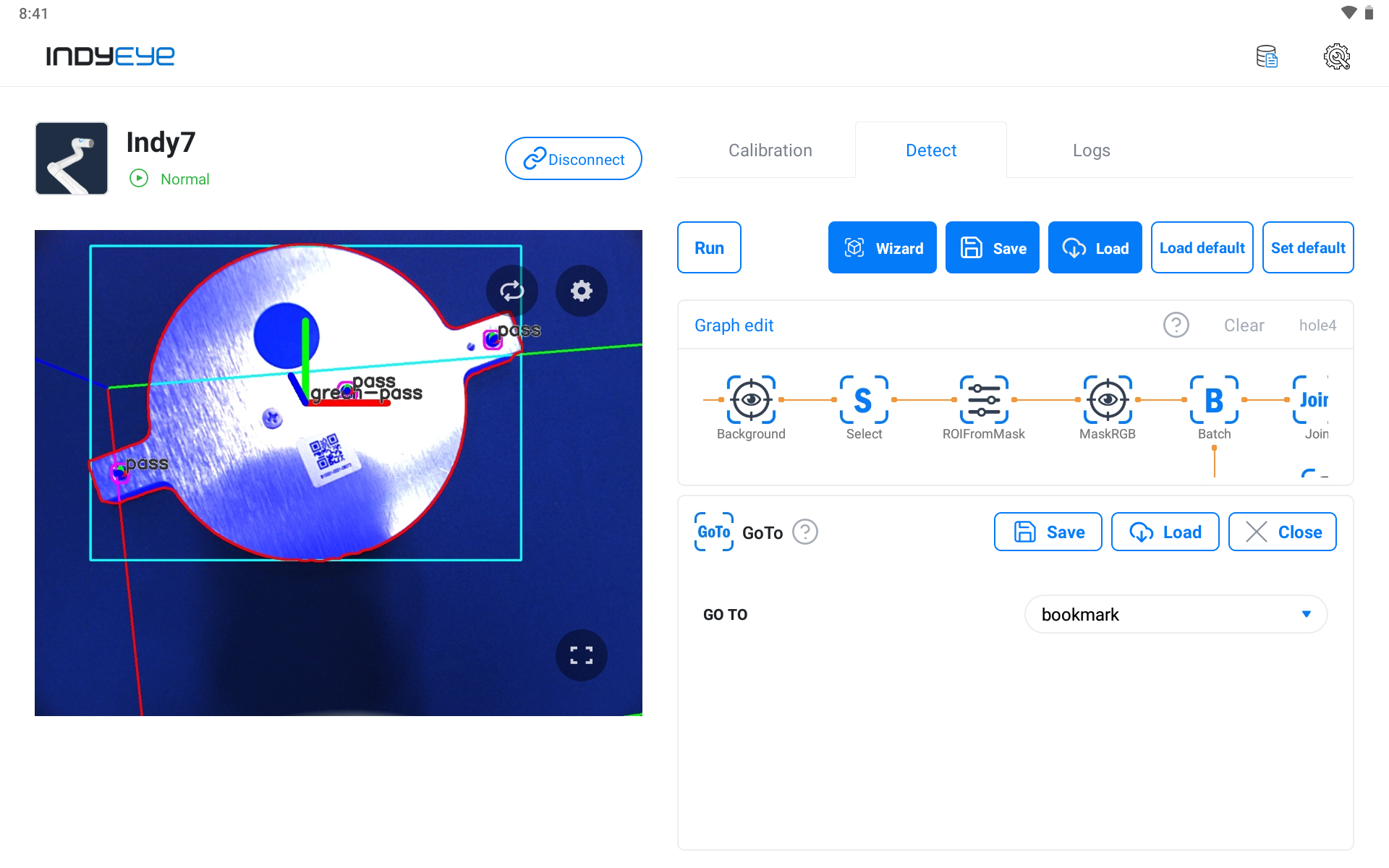
If the sticker examination has failed, it is moved to the GoTo module, then to the Join module and the graph is finished.

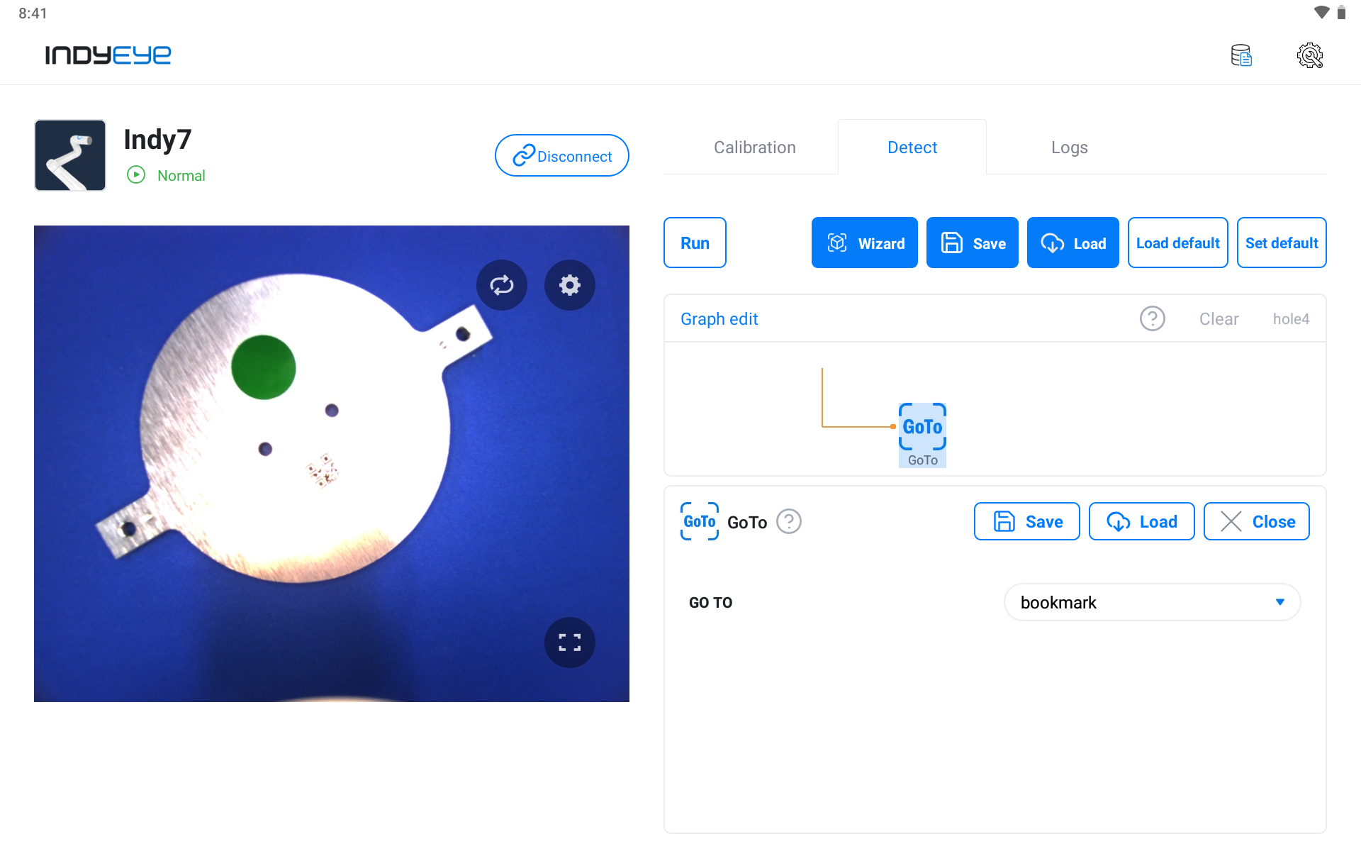
Join, GoTo Module Settings
Before working on the hole inspection, remove the sample object from the camera view and click the RECORD button in the Background module to record the background image.
Note that if the sample object doesn't exist within the view, the passed = True condition of the If module cannot be satisfied. To allow entrance to the Background module, change the parameters of the If module to passed != True. Restore the parameters to passed == True after recording the background image.
After recording the background image, the difference between the recorded background image and the current camera image will be recognized as the target object. To improve the ROIFromMask module's result mask area, modify the parameters of the Background module like the screenshot below.
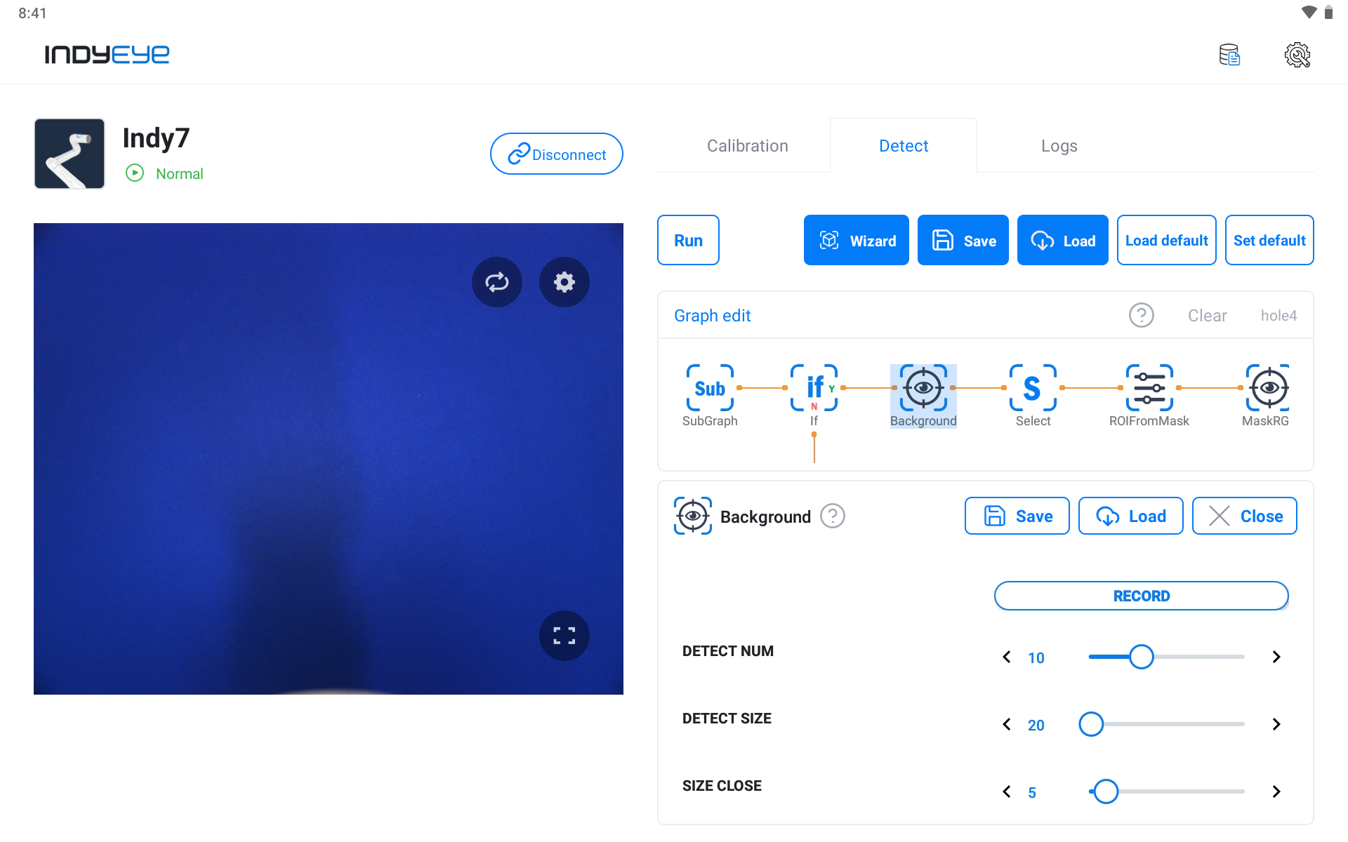
Background Module Detailed Settings
After finishing the prior stage, set the MaskRGB module to detect holes. In this example, the color of the hole area is very dark, so BLUE, GREEN, RED are all set to 0 as shown below. However, if you have a different background or specimen from the example shown, you can adjust the detailed settings to your own environment.
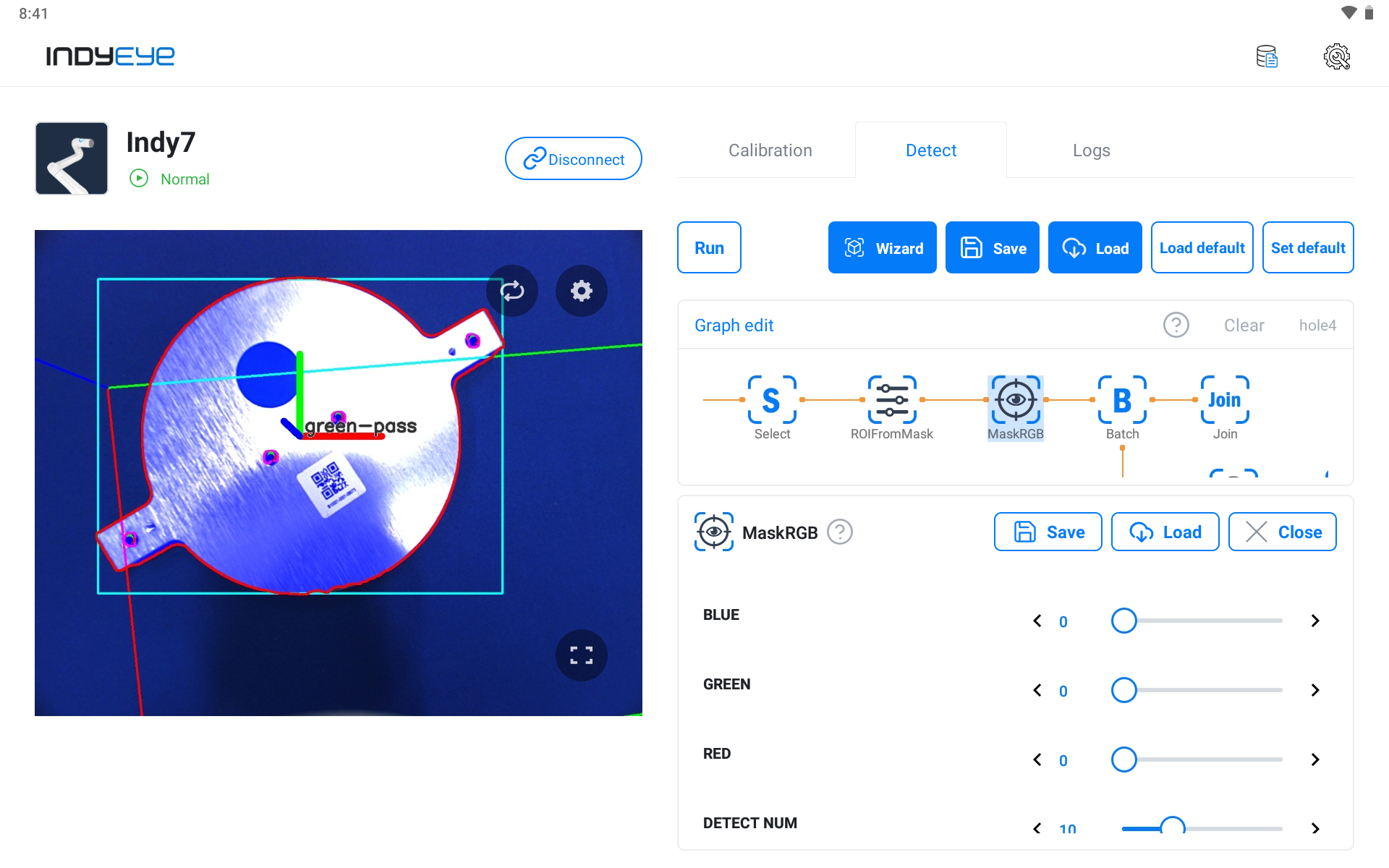
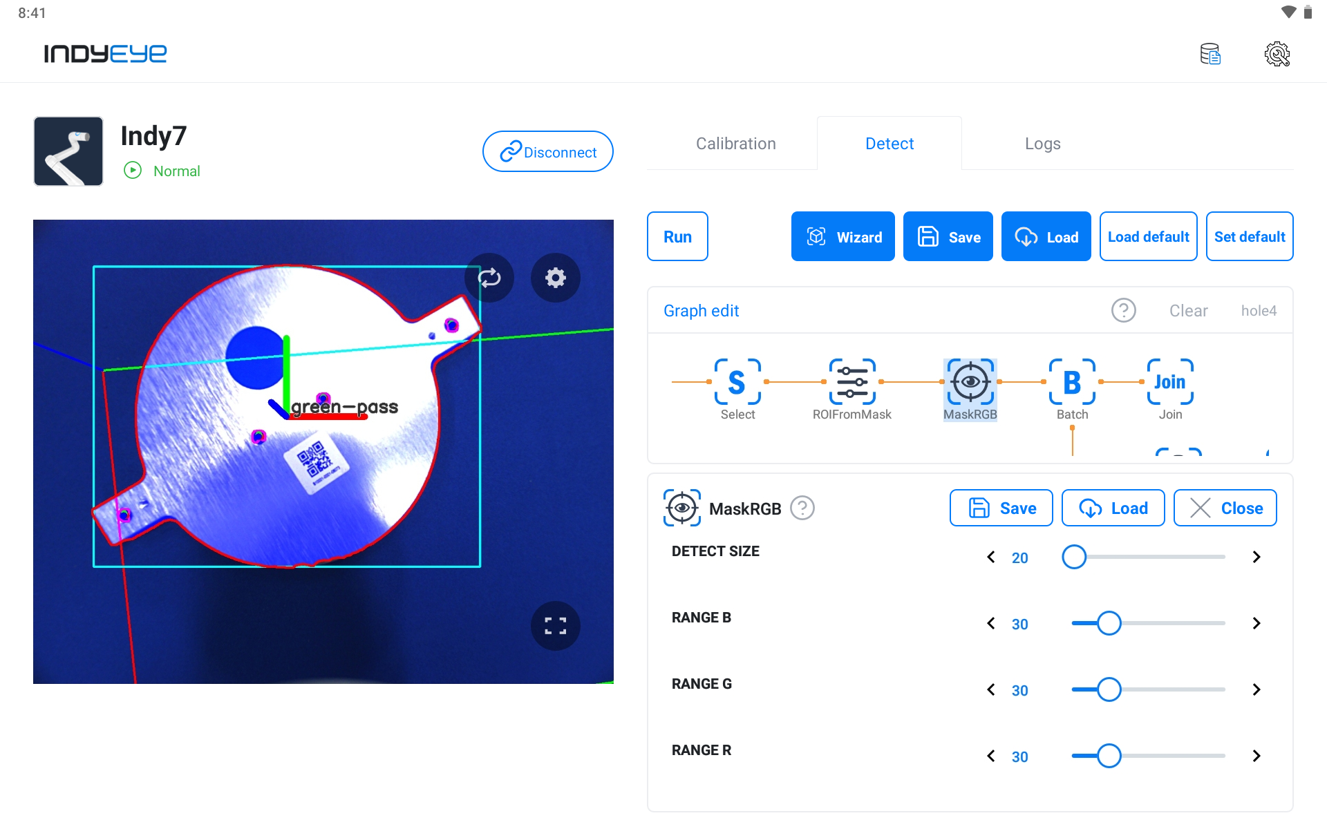
MaskRGB Module Detailed Settings
If there are many holes, the Batch module should be added. Inspection on every detected object is proceeded with pipelines while Batch is executed. First, activate DROP FAIL of Batch to remove objects that failed the inspection, and enable DilateMask and Circularity settings.
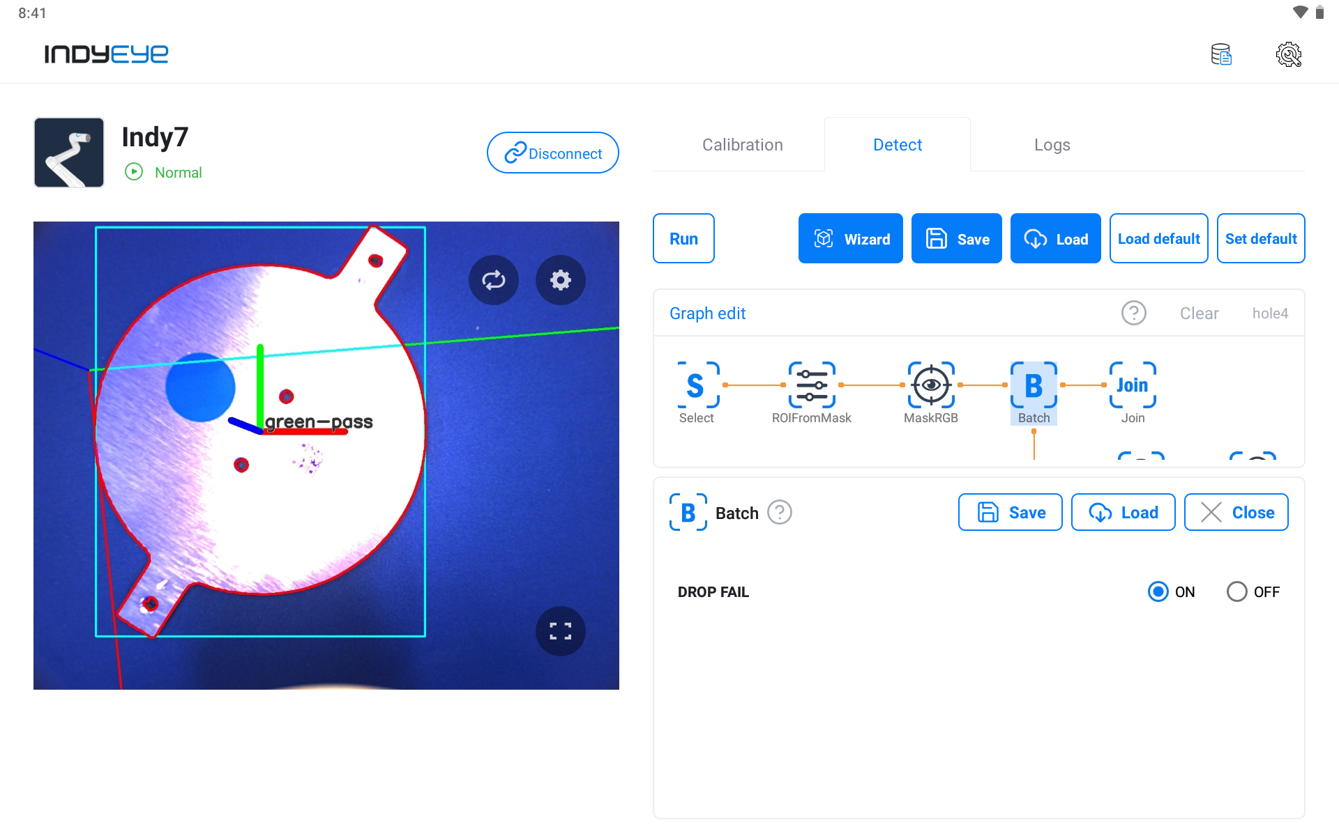
Batch Module DROP FAIL activation
Adjust SIZE DILATE of DilateMask to the hole size to adjust Mask to the hole size detected by MaskRGB. Then, adjust CUT of Circularity to increase the detection rate for more precise detection of round holes.
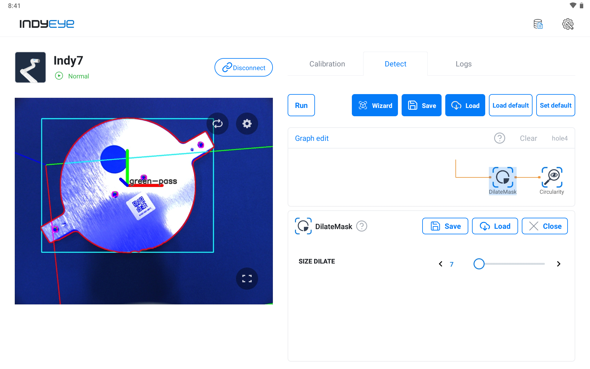
DilateMask Module Settings
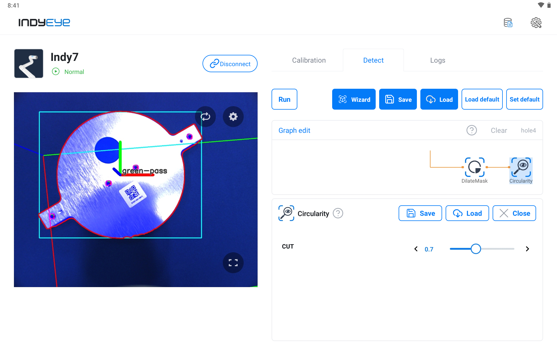
Circularity Module Settings
Now the whole graph composition is complete, and you can check the result by clicking the Execute button as shown below.
Hole Inspection Result
With the normal detection of a round sticker from the previous example, you can check that the pass sign was marked on three normally drilled bolt holes out of four holes.
