CORE Example
1. EtherCAT Slaves
In this tutorial, as shown in Figure, a set of COREs (Smart Actuator developed by Neuromeka) and IO modules from Neuromeka and Beckhoff are used. The detailed information of those components is summarized in the Table.
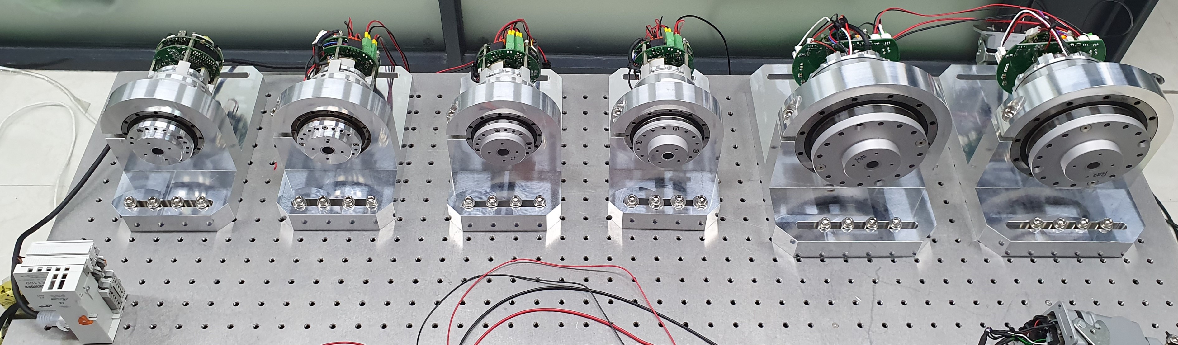
| Device Type | Description | Amount | Neuromeka IO module | AIO and DIO interface | 1 |
|---|---|---|
| CORE 500 | Ø142 x 155 mm, 500 Watt | 2 |
| CORE 200 | Ø90 x 145 mm, 200 Watt | 1 |
| CORE 100 | Ø80 x 135 mm, 100 Watt | 3 |
| Beckhoff EK1100 | EtherCAT Coupler | 1 |
| Beckhoff EL3004 | Analog input terminal | 1 |
EtherCAT system configuration
2. Physically Connecting EtherCAT Slaves to the Master
The EtherCAT network topology in this demonstration is depicted in Figure, where all EtherCAT slaves are connected serially from EtherCAT master port of STEP to Beckhoff encoder module. The order is not important but you had better follow the order to keep consistency with the remainder of this guide.

Example of an EtherCAT Topology
3. Scanning for EtherCAT Slaves
Once slaves are connected completely, log in to the STEP using PuTTY (or other SSH client tool). You can check EtherCAT slaves on the current EtherCAT bus using following terminal command. If you are not logged in as a super user, you have to prepend the command “sudo”.

You can see a list of existing EtherCAT slaves.
- NRMK IO Module: Neuromeka's anaolog and digital I/O module
- NRMK Drive: Smart Actuator CORE
- EL3004 4K.Ana. Eingang +/-10V: Beckhoff I/O board
4. Excute EtherCAT Tool
The next step is to export all slave information to the host PC because EtherCAT slaves are connected to the STEP platform, not the host PC. To this end, you first have to execute NRMKEcatService as follows.
$ NRMKEcatService
EcatInfo server started at IP of: ,127.0.0.1,192.168.1.92 on Port: 8888
Waiting for Configuration Tool to connect...
NRMKEcatService collects all necessary information about EtherCAT slaves and gets ready to send this information to EtherCAT Tool (abbreviated hereinafter by EcatTool) via socket connection. You can notice that NRMKEcatService opens a TCP server at port 8888 and is waiting for the EcatTool to connect.
Then, Execute EcatTool from NRMK Launcher in the host PC. For successful configuration of each slave, EcatTool should be aware of more detailed information on the slaves, provided by the so-called ESI (EtherCAT Slave Information) file in the form of XML format. By convention, every slave vendor provides proper ESI files for their slaves. EcatTool will search the corresponding ESI file to a specific slave on the bus among its available ESI files. It is necessary to import all ESI files for the current slaves in the designated folder for EcatTool as follows.
- Make sure there exist necessary ESI files in path below
- If there is no ESI file of slave devices, obtain the ESI from vendor and place the ESI file in location below
Notes
If EcatTool is not installed on your host PC, please find installation file in Download Page and install EcatTool.
Now EcatTool is ready to configure the current EtherCAT system interface. Selecting ‘Searching System Information’ menu on ‘Online Mode’ as shown in Figure, you are required to specify the TCP connection. Next, insert the proper IP address of the STEP platform, and click Connect button (Port: 8888).

Searching for EtherCAT System Information on EtherCAT Tool
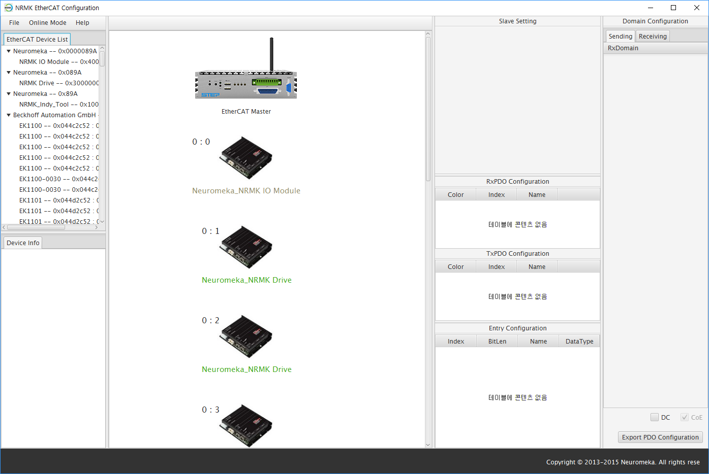
If you successfully connect to NRMKEcatService, you will see the result in Figure, which shows a list of imported slaves and their information. If the dialog is closed, you are ready to set and configure the slaves as instructed in following sections.
5. Setting EtherCAT Slave
This section describe how to set attributes of EtherCAT slaves for favorable code generation. First of all, click each slave icon to display its information in Slave Setting panel at the top of the third column. Here, the attributes you can modify are the slave icon, the vendor and the slave name as well as the alias and position of the slave (Figure).

- Icon: Slave image can be changed by Change Icon
- Vendor, Slave Name: must start with an alphabet character and contain contain alphabets, numbers, or spaces.
- Alias, Position: It is not recommended for you to change the automatically generated alias and position of slaves because they should be matched with the system topology.
Warning
Variable name is generated by combining Vendor and Slave Name during automatic code generation. C++ variable name must start with an alphabetic character, and you cannot use symbols other than underscores (_), so you should keep this in mind when creating Vendor and Slave Name. e.g., Vendor: Beckhoff, Slave Name: EL3004.
Notes
Beckhoff EK1100 EtherCAT coupler can be removed from the slaves because it plays no role in the control code.
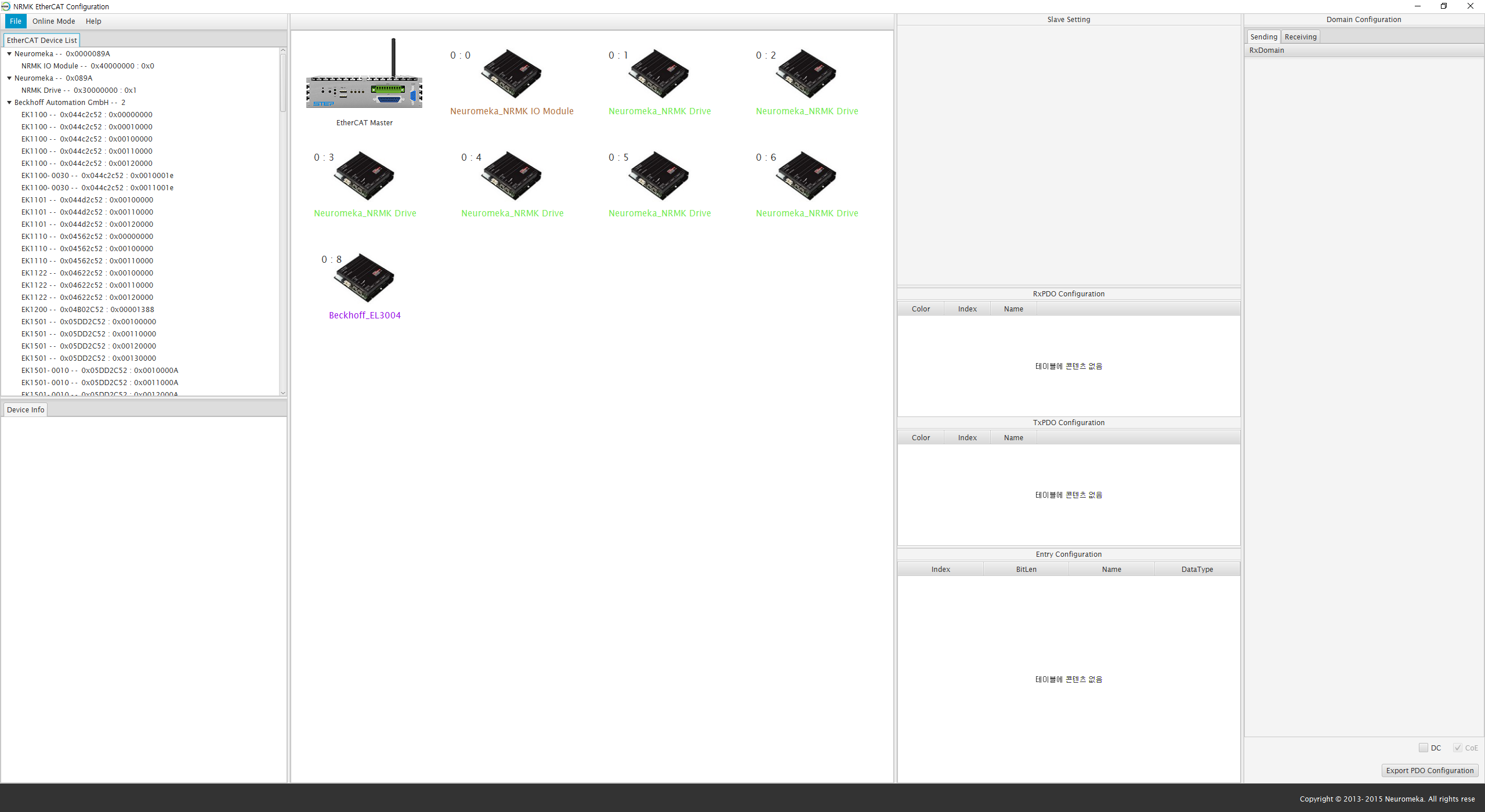
The final result is shown in Figure. Now you can go on to PDO configuration and mapping in the next sections.
6. Set PDO Entries and Domain Configuration
The setting of physical slaves has been done in the previous section. However, it does not mean that the master knows which PDOs should be transmitted to and received from slaves. The EtherCAT master should configure a number of domains (sets of PDO entries), at least one, for data communication with slaves.
The purpose of this section is to configure EtherCAT domains which contain PDO entries for cyclic communication. In EcatTool, you can see the list of available PDO mappings on RxPDO and TxPDO Configuration 1 panels when you click on any EtherCAT slave. Figure displays the PDO configuration of CORE and Beckhoff module, EL3004, respectively. They are usually called predefined PDO mappings. Note that this information has been parsed from the associated ESI file by EcatTool.
-
PDO entries of CORE: Three RxPDO (0x1600, 0x1601, 0x1602) and three TxPDO (0x1a00, 0x1a01, 0x1a02)
-
PDO entries of Beckhoff EL3004: Five TxPDO(0x1a00, 0x1a01, 0x1a02, 0x1a03, 0x1a04)

List of the PDO mappings of (a) CORE and (b) EL3004
Mapping CORE PDO Entries
If you click on any PDO mapping, the default PDO entries in the (predefined 2) mapping will be listed in Entry Configuration panel. First, start with RxPDO 0x1600 whose entries are shown in Figure. The check button on the left of RxPDO 0x1600 means that the PDO will be chosen to map some or all of its PDO entries in the domain configuration. If you want to map at least one PDO entry belonging to the PDO, it is mandatory to choose it first.

List of entries belonging to RxPDO 0x1600
In the list of entries, Targetposition, Targetvelocity, and Targettorque are related to CST (Cyclic Synchronous Torque), CSP (Cyclic Synchronous Position) and CSV (Cyclic Synchronous Velocity) mode respectively. Each mode is executed by altering the operation mode, so it requires cyclic update of Target Position, Target Velocity, and Target Torque according to the chosen mode 3.
They are defined in the PDO dictionary of the ESI file for the CORE drive, and as in Entry Configuration panel, you can see Target Position of index 0x607a, Target Velocity of index 0x60ff, and Target Torque of index 0x6071, which belong to the RxPDO mapping 0x1600.
The next step is importing some or all PDO entries into a domain 4. Select all the necessary entries you want to import, right-click and select the "Add to Domain" menu. Then, all selected entries will be imported automatically into RxDomain (Sending from the master) as shown in Figure.
Finally, you also need to import the TxPDO entries. For this tutorial, select TxPDO 0x1a00 because it contains all important entries such as actual position, actual velocity, actual torque, and so on. Then, add the entries of TxPDO 0x1a00 to TxDomain (Receiving by the master) as shown in Figure.

Importing RxPDO entries into RxDomain

Importing TxPDO entries into TxDomain
Mapping Beckhoff EL3004 PDO Entries
As shown in Figure, Beckhoff EL3004 consists of only TxPDO lists. For this tutorial, import the TXPDO 0x1a00 entries into domains. This can be done in the same way as CORE in the previous subsection.

Mapping IO Module and End Tool (NRMK_Indy_Tool) PDO Entries
As shown in Figures (a) and (b), the IO Module provides only one RxPDO and TxPDO: 0x1610 and 0x1A10. Similar to the previous slaves, all RxPDO and TxPDO entries are imported.

(a), (b) IO Module RxPDO and TxPDO
7. Generating EtherCAT Project in Eclipse
Now, you have finished configuration of EtherCAT system interface and are ready
to generate realtime code for the current system. You can click Export PDO Configuration
button to start generating C++ code for realtime control.
System Setting dialog appears to specify your C++ project name.
In the dialog, System Name is the name of the Eclipse C++ project, and Control Period is the period of one realtime cycle, which is 1 (ms) by default (Figure). Furthermore, select Platform PC option if you are using STEP/PC or STEP/HPC (all based on Intel x86 architecture), or Platform IMX for STEP/iMX or STEP/BBB (all based on ARM architecture).

Setting C++ Project on Eclipse
Clicking OK button displays EtherCAT PDO Generator dialog as in Figure. You may review the generated C++ code before exporting it to source files.

To generate the source codes and the project, click the File menu and select Export as shown in Figure. In the Save As dialog shown in Figure, please make a new folder (e.g. EcatDemonstration) in the workspace of NRMKPlatform. For STEP/PC, the directory is as follows:
Then, click Save to generate all project codes.

Exporting C++ Project to NRMKPlatformPC's workspace
8. Compiling and Executing Eclipse Project
This section describes how to compile and execute your EtherCAT realtime project using Eclipse. After executing Eclipse, click the File and Import menu as shown in Figure.

In the Import dialog, select Existing Projects into Workspace option as shown in Figure.
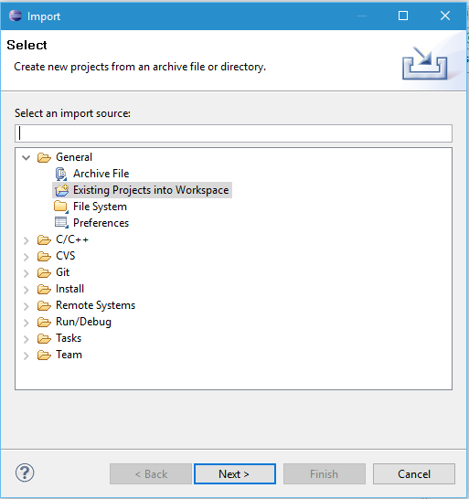
Selecting Existing Projects into Workspace
Then, specify the directory where you put the source files in the previous section in Select root directory field. In this example, it is:
If the directory is correctly selected, your EtherCAT project will be shown in Projects list as shown in Figure.

Specifying EtherCAT Project Directory
Now, click Finish button, and you will have your project listed in Eclipse’s Project Explorer. See the Figure.

EtherCAT Project listed in Eclipse's Project Explorer
Before compiling the project, set Build Configuration to Release as described in Figure in order for Eclipse to generate release version of the EtherCAT application. Please refer GCC Compiling manual for more information about Release and Debug mode.

Setting Build Configuration to Release
To compile the EtherCAT project, click Project | Build Project menu as shown in Figure. When you see the message shown below in Console window of Eclipse, your project has been built successfully.

Compiling EtherCAT Project in Eclipse
9. Executing EtherCAT Application
This section describes how to execute remotely your EtherCAT Application on STEP/PC. To this end, you should specify a remote target (e.g. STEP/PC) and create Run Configuration to determine how Eclipse executes your application on the remote target.
First, click the Remote System menu on the top right of Eclipse to set the remote target. In the Remote System panel, select Target and replace its Host Name with the IP address of your target. The procedure is fully described in the Figure below.

Specifying Remote Target on Eclipse
Second, click the C/C++ menu to go back to the normal user interface. Click Run | Run Configuration to open the Run Configuration dialog (Figure).
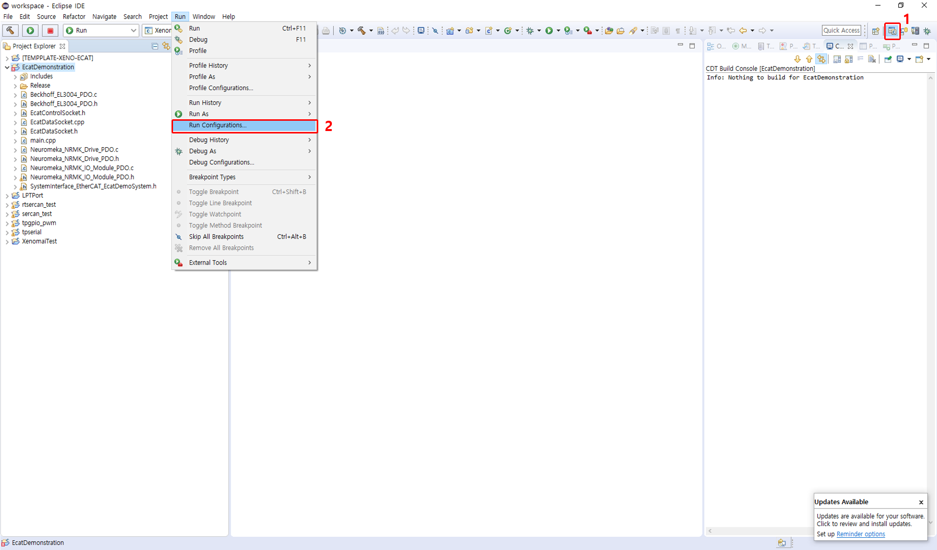
In the Run Configuration window, click new button to create a new configuration
and fill the fields in Main tab as same as Figure.
Finally, click run button at the bottom to execute your EtherCAT application.

Specifying Run Configuration for EtherCAT Application
If everything works well, you will see the console message on Eclipse like Figure below.

EtherCAT Application's real-time message
-
The term ‘RxPDO’ and ‘TxPDO’ come from the slave viewpoint. That is, the PDOs received by slaves may form an RxPDO, while those transmitted from slaves form a TxPDO. In general, the commands to the slaves may belong to RxPDOs and the states of the slaves to TxPDOs. ↩
-
As the name ‘predefined’ implies, you can change the entries as long as the total number of entries are kept. ↩
-
CSP, CSV, and CST modes requires that the target position, velocity, and torque values be updated explicitly every cycle. There are a number of other modes defined in EtherCAT, e.g. IP (Interpolated Position), PP (Profile Position), and the like. Neuromeka's CORE only provides CST mode. ↩
-
EtherCAT Tool provides two domains by default: one for RxPDOs (sending from the master) and the other for TxPDOs (received by the master). ↩
