Digital, Analog I/O
Input/Output with I/O Board and End-Tool Port
This chapter introduces how to use digital and analog inputs/outputs with the I/O board mounted on the robot control box and the end-tool port mounted at the end of the robot.
The I/O board is attached to the front panel of the control box and can use digital I/O and analog I/O. The end-tool port is mounted at the end of the robot and allows cable connections through the port, supporting digital I/O, analog I/O, and CAN communication.
Access to these input/output signals is possible through Conty or Indy API.
Acronyms
- Digital Input, Digital Output: DI, DO
- Digital Input/Output: DIO
- Analog Input, Analog Output: AI, AO
- Analog Input/Output: AIO
I/O Board
The figure below shows the port configuration of the I/O board mounted on the control box. It consists of a total of 32 channels of DIO, 8 channels of 5V DIO, and 4 channels of AIO.
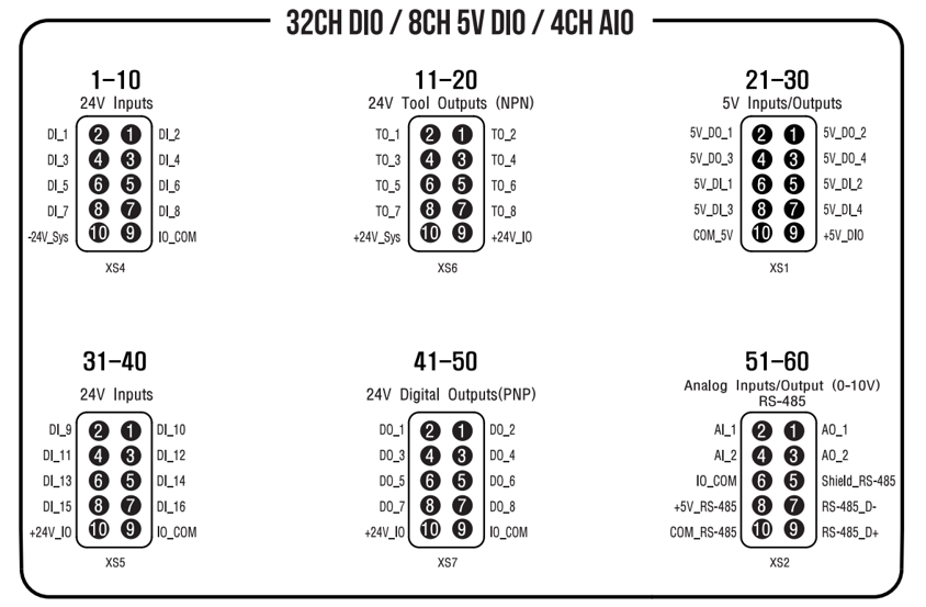
I/O Board Port Configuration of IndyCB
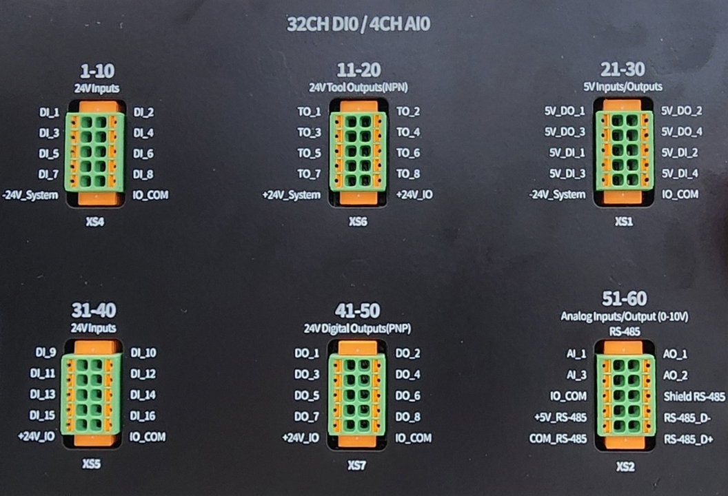
I/O Board Port Configuration of IndyCB (Photo)
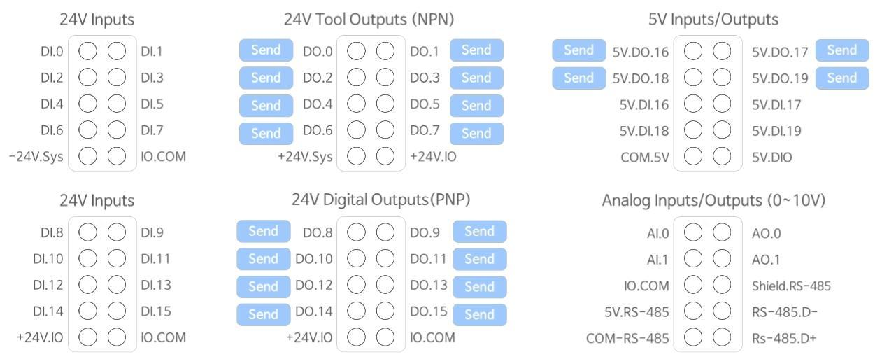
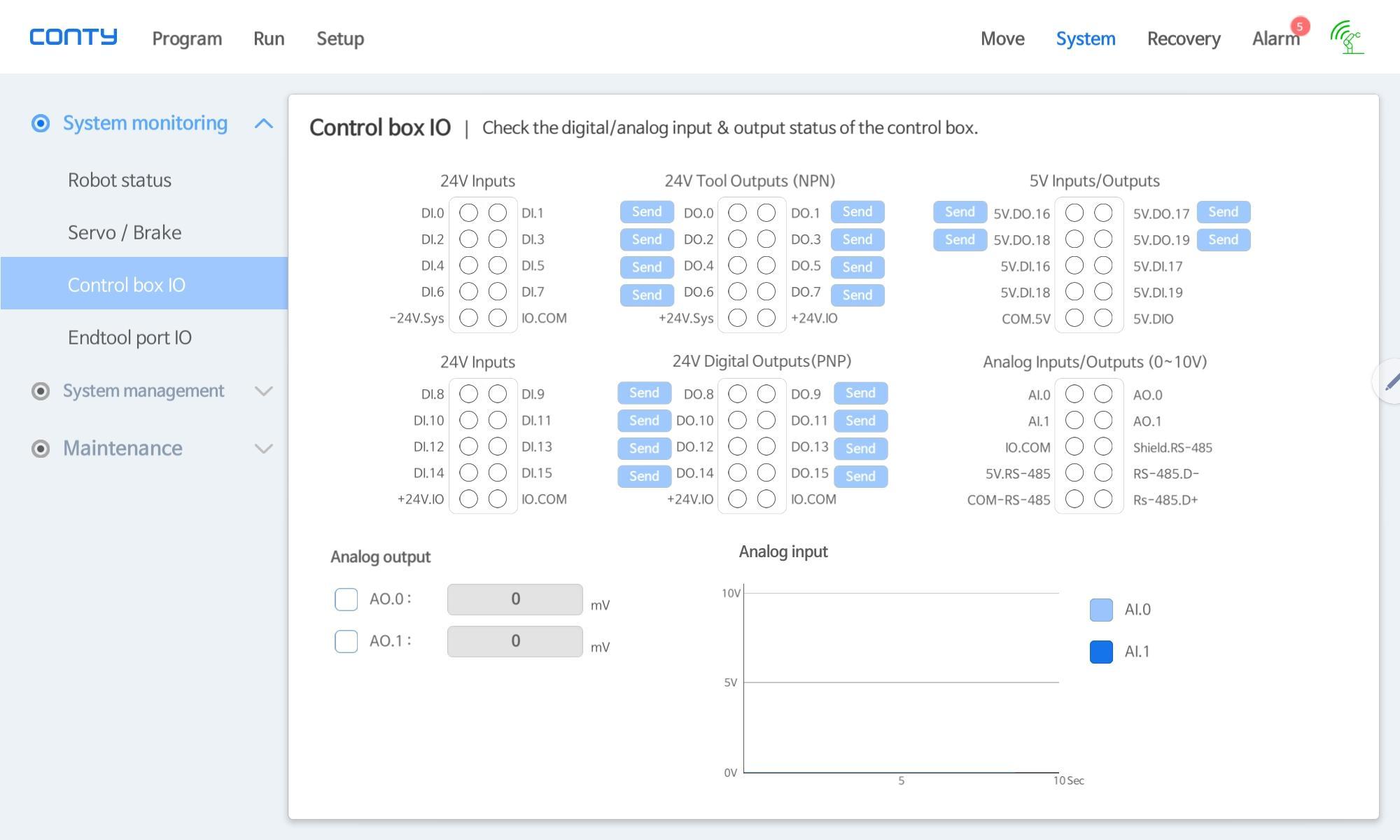
I/O Board Port Configuration of IndyCB (Conty Capture)
Note
Depending on the production version of IndyCB, the index printed on the IO board panel and the index shown in Conty may differ. In such cases, the index shown in Conty should be used as the reference.
- 16 channels of 24V DI
- 16 channels of 24V DO (NPN Tool Outputs and PNP DO)
- 8 channels of 5V DI
- 8 channels of 5V DO
- 2 channels of 0-10V AI
- 2 channels of 0-10V AO
Digital Input/Output of I/O Board
There are 32 inputs and 32 outputs for DIO (00-31), and the information of each DIO port and pin mapped to each DIO number is as follows:
| DIO Index | Mapped Port Name | Pin Name |
|---|---|---|
| DI[0] - DI[15] | 24V Digital Inputs Port | DI_1-16 |
| DI[16] - DI[19] | 5V Digital Inputs Port | 5V_DI_1-4 |
| DO[0] - DO[7] | 24V NPN Tool Outputs Port | TO_1-8 |
| DO[8] - DO[15] | 24V PNP Digital Outputs Port | DO_1-8 |
| DO[16] - DO[19] | 5V DO Port | 5V_DO_1-4 |
Note
The value of DIO is HIGH (1) or LOW (0), the same as commonly used in general DIO.
Analog Input/Output of I/O Board
There are 4 inputs and 4 outputs for AIO (00-03), and the information of each AIO port and pin mapped to each AIO index is as follows:
| SmartAIO Index | Mapped Port Name | Pin Name |
|---|---|---|
| AI[00] - AI[01] | 0-10V Analog Inputs Port | AI_1-2 |
| AO[00] - AO[01] | 0-10V Analog Outputs Port | AO_1-2 |
Note
The value of AIO is an integer from 0~10000, where 0 represents 0V, and 10000 represents 10V.
End-Tool Ports
The number of end-tool ports varies depending on the version of the robot.
- Indy7, Indy12, IndyRP2: RevC end-tool port, 1 port
- Indy7v2, Indy12v2, IndyRP2v2: RevE end-tool port, 2 ports
RevC end-tool port
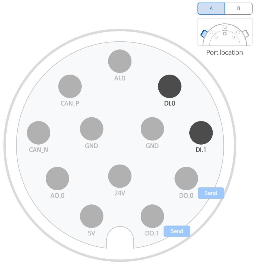
RevE end-tool port-A
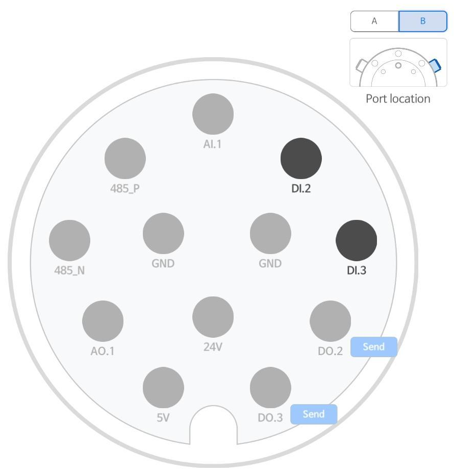
RevE end-tool port-B
Digital Input/Output of End-Tool Ports
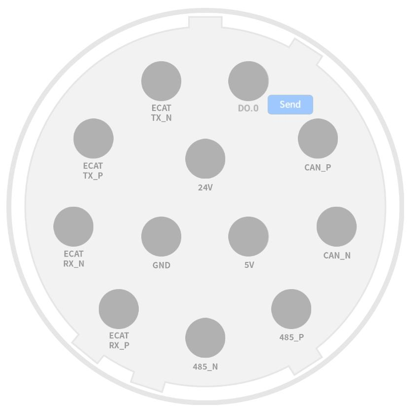
RevC End-Tool Port
The RevC end-tool port provides 1 DO channel. NPN and PNP settings can be changed as needed. Refer to the figure for the pin map.
| Index | Mapped Port Name | Pin Name |
|---|---|---|
| - | Digital Output | DO.0 |
| - | +24V DC | 24V |
| - | +5V DC | 5V |
| - | GND | GND |
RevE End-Tool Ports
The RevE end-tool ports provide 2 DI channels and 2 DO channels each for ports A and B. NPN and PNP settings for DIO can be changed as needed. Refer to each pin map for ports A and B (port A, port B).
Note
The allowable current of the end tool port is defined as the sum of the currents of ports A and B, and it must not exceed 3 A at 24 V and 0.5 A at 5 V.
Analog Input/Output of End-Tool Ports
AI and AO exist only on the RevE board, with each port A and B providing 1 AI channel and 1 AO channel, thus offering 2 AI channels and 2 AO channels in total. Refer to each pin map for ports A and B (port A, port B).
CAN Communication of End-Tool Ports
CAN ports are provided for grippers that need to be controlled via CAN communication. CAN communication is available for both RevC and RevE ports.
RS485 Communication of End-Tool Ports
Controlling I/O Using Conty
In Conty, under 'System-Control Box IO', you can check the Port&Pin Map of the I/O board as shown in the picture below and control inputs/outputs accordingly.
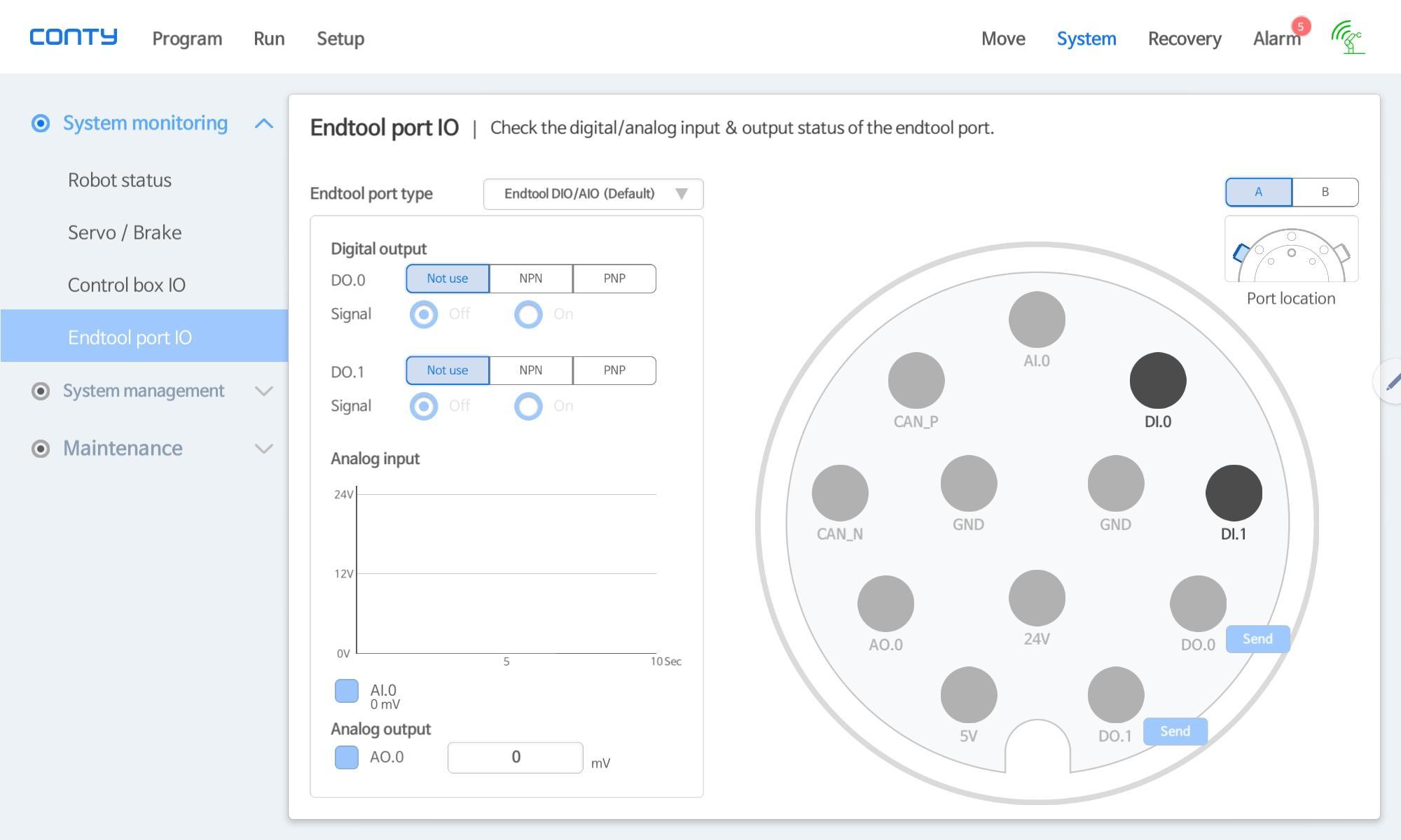
Similarly, under 'System-End-Tool Port IO', you can check the Port&Pin Map of the I/O board and control inputs/outputs as shown in the picture below.
For detailed usage, please refer to the Indy User Manual.
Controlling I/O Using Indy API
Control of DIO and AIO is not limited to Conty but can also be achieved through Indy API's offerings: IndyDCP3, Modbus TCP, and IndyDCP2.
