Getting Started
Features and Specifications of Moby-RP
Moby-RP (Research Platform) is a research robot platform that integrates a mobile manipulator robot, Moby, a collaborative robot, Indy, and a robot vision solution, IndyEye. Moby-RP provides mobility to a non-mobile collaborative robot and can be used for various purposes such as manufacturing, logistics, delivery, patrol, disinfection, and guidance. In addition, it can be used as an agricultural or service robot by combining various equipment such as a lift or serving tray.
Moby-RP uses SLAM (Simultaneous Localization and Mapping) and navigation algorithms through obstacle detection using LiDAR, 3D object recognition using RGB-D sensors, and close obstacle detection using IR sensors with ToF method. It can autonomously navigate by avoiding obstacles. In addition, various sensors can be mounted by changing the sensor plate.
Moby can be driven by a swerve drivetrain, which consists of a steering wheel that can steer (infinite rotation) and drive forward and backward. Each wheel module is driven by a steering motor and a drive motor, totaling eight drive motors. The swerve drivetrain minimizes the power deviation, resulting in excellent straight-line control and enabling omnidirectional movement. The eight-axis drive motor of the swerve drivetrain, six joints of Indy7 (or seven joints of IndyRP2), I/O board, robot end tool are a total of 16 (or 17 in the case of IndyRP2) EtherCAT slaves, each of which is synchronized by EtherCAT master, STEP3.
The hardware configuration of Moby-RP is as follows:

Moby configuration
| No. | Name | No. | Name |
|---|---|---|---|
| 1 | RGB-D sensor (4ea) | 8 | Battery level indicator |
| 2 | LiDAR sensor (2ea) | 9 | Emergency stop button (2ea) |
| 3 | IMU sensor | 10 | Front wheel |
| 4 | ToF IR sensor | 11 | Rear wheel |
| 5 | USB port | 12 | Speaker |
| 6 | Emergency power port | 13 | LED indicator |
| 7 | Charging port | 14 | Power button |
Moby Coordinate System Configuration
The coordinate system of Moby is expressed as follows:
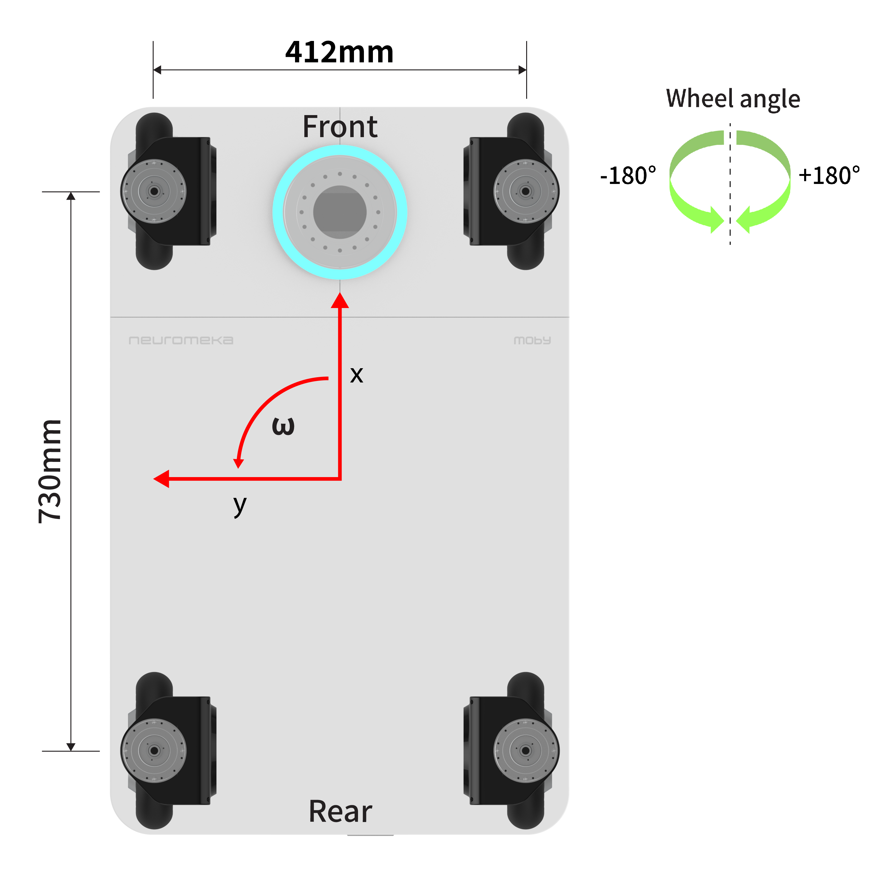
The coordinate of the chassis of Moby is expressed as (x, y, \omega). The position of Moby with respect to the reference coordinate system is represented as (P_x, P_y, P_\omega), and the velocity is represented as (V_x, V_y, V_\omega). The rotation inertia is defined counterclockwise as the positive direction, and the steering angle of each wheel module is defined as the clockwise rotation as the positive direction.
Moby SW Framework Configuration
Moby-RP is operated by two control PCs.
- STEP3: Real-time control of motor drives, IO boards, and end tool boards, Signal processing of IMU sensors and IR sensors. IndyEye image processing
- NUC: 3D camera image processing, LiDAR based SLAM / Navigation
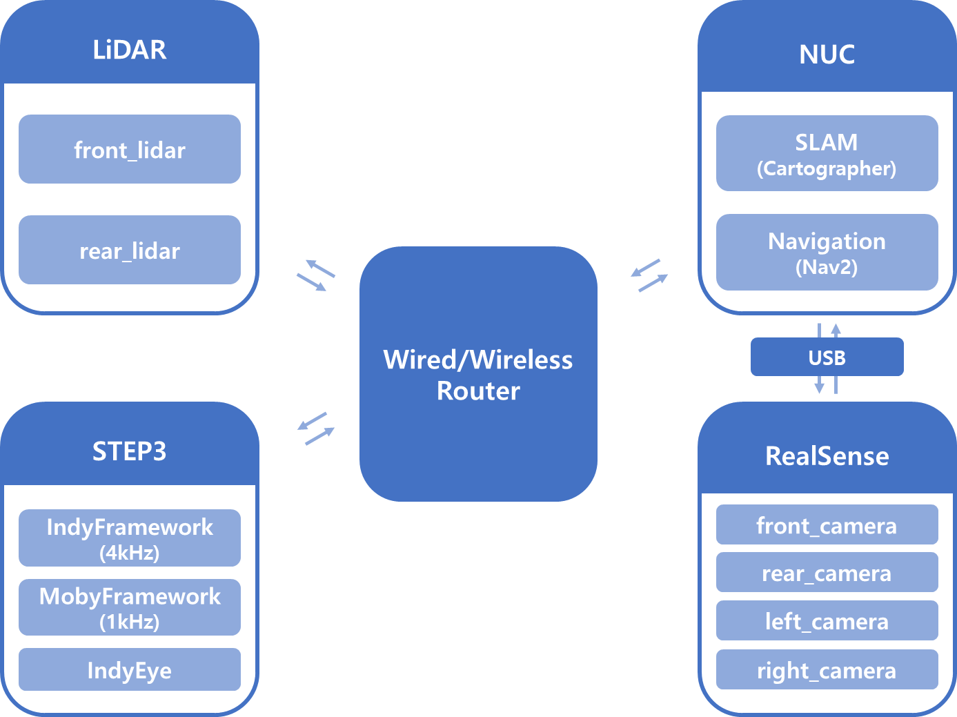
Communication Diagram
STEP3 and NUC are connected as shown below to exchange data between them.
Connecting to Moby
The IP address and port information of Moby are provided to an external PC through Moby's router, which can be used to connect to Moby from an external PC. STEP3 and NUC have fixed IP addresses (192.168.214.20), which can be verified through the information provided at the time of delivery. After that, you can control and monitor Moby using STEP3 and NUC.
- STEP IP: 192.168.214.20
- NUC IP: 192.168.214.21
