Introduction
Overview
LabVIEW Toolbox includes a sample Indy VI (Virtual Instrument) named IndyComm.vi and a DLL library for Indy interface. The DLL file is used by the Indy VI to communicate with Indy Framework via TCP socket protocol. The figure describes the whole LabVIEW Toolbox for an Indy robot
-
IndyLV Project : C++ project for shared library of Indy interface. (The library implements functions to communicate with Indy Framework via socket connection.)
-
IndyLV.DLL : Compiled IndyLV project used by the LabVIEW VI directly.
-
Indy LabVIEW VI : Sample LabVIEW VI for users to know how the library works. (Based on it, they can add more components or make a new one by themselves.)
-
Indy Framework 2.2.2 : Set of binary files to operate an Indy robot. (It is delivered to customers when they purchase the Indy.)

Installation
The LabVIEW Toolbox is freely available from the Github repository
Use your favorite Git tool to clone the repository. Then, you will have these files and folder in your directory;
-
IndyLV : Visual Studio C++ source folder of the shared library IndyLV.dll
-
IndyLV.dll : The shared library file compiled from IndyLV project used by LabVIEW VI.
-
IndyComm.vi : A sample of LabVIEW VI, which uses IndyLV.dll to communicate with Indy Framework.
Configuration
The LabVIEW Toolbox operates on computers with NI LabVIEW installed. It is compatible with most of LabVIEW versions. Furthermore, the toolbox requires Ethernet connection to STEP in order to transfer commands and robot state. After installation, the LabVIEW Toolbox can be used immediately without any further configuration.
User Access Levels
Everyone can use, modify, and develop functions of LabVIEW Toolbox.
Project References
References used for preparation of this document in order of importance to the end user.
Organization of the Manual
The user's manual consists of four sections:
-
General Information : section explains general terms of the system and the purpose.
-
System Summary : section provides a overview of the system. The summary outlines the uses of the system hardware, software requirements, system configuration, and user access levels.
-
Getting Started : section explains how to get the Indy packages and install them on the device.
-
Exploring the System : section provides a detailed description of system functions and components.
Acronyms and Abbreviations
Provide a list of the acronyms and abbreviations used in this document and each meaning.
-
Indy : All types of Indy robot
-
Indy DCP : Indy Dedicated TCP/IP Protocol
-
STEP : The embedded controller of Indy.
-
VI : Indy Virtual Instrument in LabVIEW
-
UI : User Interface
-
q : Robot's Joint-space Position (radian)
-
qdot : Robot's Joint-space Velocity (radian/s)
-
qddot : Robot's Joint-space Acceleration (radian/s2)
-
6D Space : 3D displacement & 3D orientation
-
Pos / pos : Robot's Cartesian-space Position (meter + radian)
-
Vel / vel : Robot's Cartesian-space Velocity (meter/s + radian/s)
-
Acc / acc : Robot's Cartesian-space Acceleration (meter/s2 + radian/s2)
Basic Tutorial
Execution of the LabVIEW Toolbox
After installing LabVIEW, please download the DMC UI Suite1 from the link. The Indy VI uses the UI Suite to improve the skin of UI components. Then, you can make a double click on IndyComm.vi to open the sample Indy VI on your LabVIEW.
Let us take a look at the UI of Indy VI in LabVIEW front panel. At first, please pay attention on Setting area as shown in the Figure.

Setting area of shared library and socket information
-
Indy Library Path : This is the absolute path to IndyLV.dll. To get the path, you may click the open button and select the IndyLV.dll file
in the Open window. -
Socket Info : Those are necessary information of Indy DCP socket including STEP IP address, port number, and robot's name.
-
Making connection : When you run the VI, you can click Connect button to make
a connection to Indy Framework.
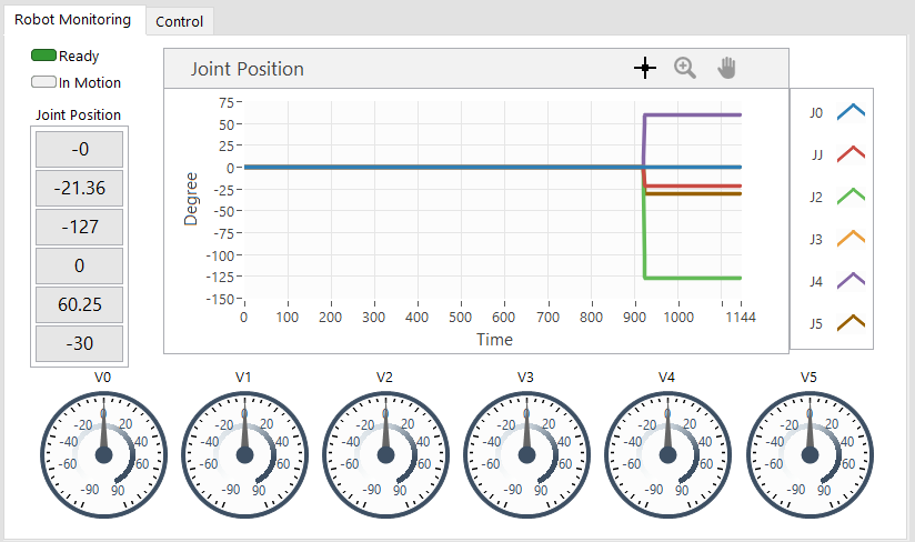
When the connection is successfully established, you will see the Robot Monitoring area as the Figure.
-
Ready : This LED indicates the robot's readiness for operation.
-
In Motion : This LED will turn green if robot is moving.
-
Joint Position : The position is displayed on both graph and numeric indicators at left-most of the area
-
Joint Velocity : The velocity is represented by gauges at the bottom of the area.
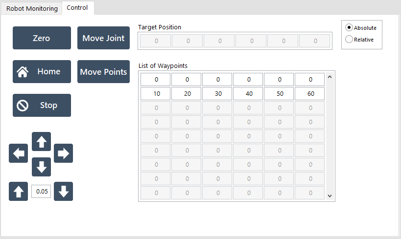
Next to the Monitoring tab is the Control tab as shown in the Figure.
-
Zero : Move to zero position (i.e. all joints' angles are zero).
-
Home : Move to Home position (i.e. Home is a pre-defined position).
-
Stop : Slow stop command
Move Joint
to the target position. -
Target Position : The target is in degree and used by
Move Joint
function. -
Move Points : Move the robot through a list of waypoints.
-
List of Waypoints : This is a 2D array of Nx6. N is the number of points and 6 is the number of robot's joints.
-
←→↑↓ : Those buttons send commands to move robot's TCP along the X, Y, and Z axis with respect to the global coordinate. Moreover, the moving distance is declared in the numeric indicator between the ↑ and ↓ button.
Examples
Indy Shared Library
As briefly explained in the section, the shared library IndyLV is developed by Visual Studio C++. This section will guide you through the source code of IndyLV project. For more details about developing shared library for LabVIEW, please refer to the appropriate URL at the above section.
The IndyLV project, which is found in the Toolbox repository, looks like the Figure in Visual Studio. As a developer, you need to pay attention on the IndySocket.h and IndySocket.cpp only. Those files declare and implement APIs called by the Indy LabVIEW VI.
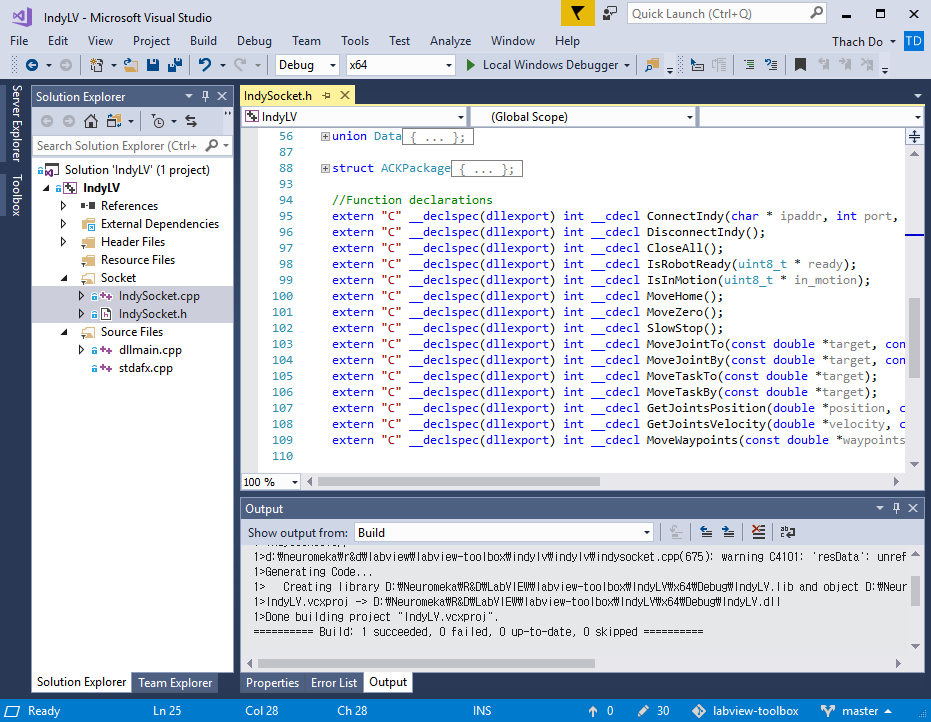
IndyLV Project in Visual Studio C++
By taking a closer look at IndySocket.h in the Code, you can see the declarations of all functions implemented for the shared library. Below list is brief description of each function. You are welcome to dig deeper into the source code for implementation of the functions.
-
ConnectIndy : Make a socket connection to Indy Framework. Parameters are IP Address, Port, and Robot Name.
-
DisconnectIndy : Close a socket connection with Indy Framework and stop all threads.
-
CloseAll : Similar to DisconnectIndy.
-
IsRobotReady : Request for robot's readiness. This function returns 1 or 0 for ready or not-ready state respectively.
-
IsInMotion : Request for robot's motion state. This function returns 1 or 0 for in-motion or not-in-motion state respectively.
-
MoveHome : Command to move robot to Home position.
-
MoveZero : Command to move robot to Zero position.
-
SlowStop : Command to stop motion within a moment.
-
MoveJointTo : Command to move robot to an absolute target position. Inputs are target position (in degree) and the number of joints (DoF)
-
MoveJointBy : Command to move robot to a relative target position. Inputs are target position (in degree) and the number of joints (DoF)
-
MoveTaskTo : Command to move robot to an absolute 6D target position. Inputs are target position of 6 components: X (meter), Y (meter), Z (meter), RotX (degree), RotY (degree), and RotZ (degree).
-
MoveTaskBy : Command to move robot to a relative 6D target position. Inputs are target position of 6 components: X (meter), Y (meter), Z (meter), RotX (degree), RotY (degree), and RotZ (degree).
-
GetJointPosition : Request for current joints' position. Input is the number of joints and output is an array of angles (degree).
-
GetJointVelocity : Request for current joints' velocity. Input is the number of joints and output is an array of velocities (degree/s).
-
MoveWaypoints : Command to move robot through a list of waypoints. Inputs are a pointer to waypoint list, the number of points, and the number of joints.
1 2 3 4 5 6 7 8 9 10 11 12 13 14 15 16 17 18 19 20 21 22 23 24 25 26 27 28 29 30 | |
Indy VI Block Diagram
This section explains elaborately the block diagram -- a graphical source code -- of Indy VI in LabVIEW. Corresponding to the UI, the Indy VI's block diagram objects are organized into two groups: Monitoring (Figure) and Control group (Figure). In those figures, there are a few common objects described below.

True/False button :
All buttons in Indy VI are set to be "latch when released".

Call-Library-Function node : It represents a DLL function called by LabVIEW VI.

Switch/Case object : In the Indy VI, it checks a button value and makes a call to the library function inside.
Loop object : It repeats the code within its sub-diagram until a specific condition occurs.

Sleep object : It suspends the loop during an amount of time (in millisecond), and the timing amount is indicated by a constant connected to the object.

This object accepts input data and visualizes them on a waveform chart. In Indy VI, the waveform chart is used for joint position display.

This object accepts a single input and display it in a gauge. In Indy VI, the gauge objects are used for velocity display.
Now, let us take a closer look into the Robot Monitoring Block Diagram. There is one loop covering 4 library calls to IsRobotReady, IsInMotion, GetJointsPosition, and GetJointsVelocity. Then, the feedback data are visualized by appropriate UI component such as LED, Waveform Chart, and gauges.
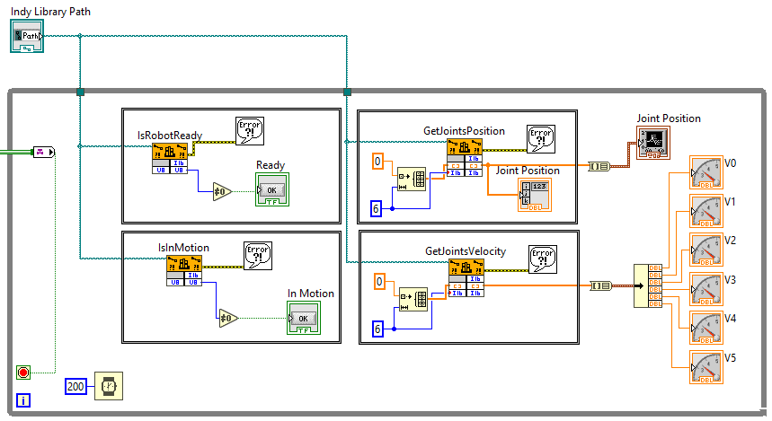
Robot Monitoring Block Diagram objects
Meanwhile, the Robot Control Block Diagram in the Figure uses its loop to poll its UI components. This loop does not need a sleeping clock because it is inactive most of the time until a UI event happens. For instance, when you click MoveHome button, it changes state from False to True and consequently triggers the MoveHome function call in the Switch/Case object. This call sends a request to Indy Framework via TCP socket to move robot to Home position.
Last but not least, a Power button is a safe method to terminate the Monitoring and Control loop and close the Indy VI finally. In this case, you can use a Tag channel to transfer the Power button's signal to the loop's termination condition.
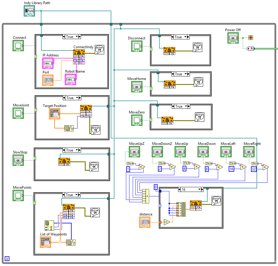
Robot Control Block Diagram objects
-
Due to the DMC copyright, the UI Suite cannot be inncluded in Neuromeka’s LabVIEW Toolbox. ↩
