Skip to content

Configuration of IndySDK

Robot Execution using IndySDK

This is guidance for those who want to run the robot for the first time using pre-built component files of IndySDK.

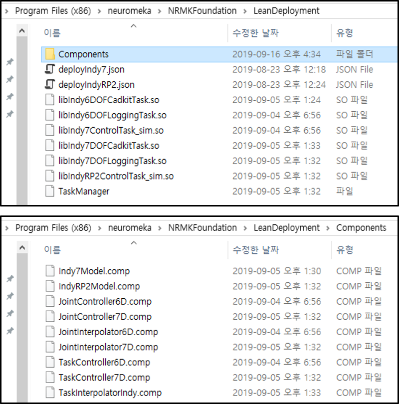
If the installation is compete, please copy the LeanDeployment folder in /neuromeka/NRMKFoundation/ directory of the development PC (Windows) to the path /home/user/release/ in STEP as illustrated in below.

Note

When users copy component files from development PC to remote server (STEP), users can use Windows Explorer or other SFTP, SCP, FTP client app such as WinSCP to perform SSH file transfer.


After completing the copy, log in to STEP using PuTTY (or other SSH client tool). Then, enter the terminal command as shown below.

  • Set execution privilege to the TaskManager file in STEP
1
2
$ cd /home/user/release/LeanDeployment
$ chmod 777 *
  • Execute the TaskManager with root privilege as below. Here, JSON deployment file deployIndy.json must be given as an argument of TaskManager.
1
$ sudo ./TaskManager -j deployIndy7.json
  • Then, the robot turns on and Indy Framework is executed, and basic console logger appears in the terminal shown in below.


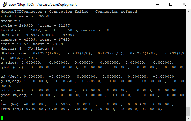
TaskManager TaskManager Display: Console Logger

  • Now, users can use Conty (teach pendant) to control the robot (or virtual robot).

Note

Please refer to IndyFramework chapter for the detailed description about TaskManager and shared library (.so file) which are execution files of Indy Framework.

JSON Deployment File

deployIndy7.json is a JSON deployment file that configures tasks when operating robot. As shown in the code below, there are three tasks to be executed when the robot operates. Each task contains components as the element of Param.

 1
 2
 3
 4
 5
 6
 7
 8
 9
10
11
12
13
14
15
16
17
18
19
20
21
22
23
24
25
26
27
28
29
30
31
32
33
34
35
36
37
38
39
40
41
{
  "TimerRate" : 4000, /*Hz*/
  "HighRate" : 4000, /*Hz*/
  "MediumRate" : 20, /*Hz*/
  "LowRate" : 1, /*Hz*/

  "Path" : "/home/user/release/LeanDeployment/",

  "QueueHigh" :
  [
    {
      "TaskName" : "Indy7ControlTask",
      "SharedLib" : "Indy7ControlTask.so", // For real robot operation
      // Use Indy7ControlTask_sim.so for simulation mode
      "Params" :
      {
        "RobotModel" : "Indy7Model",
        "JInterpolator" : "JointInterpolator6D",
        "JController" : "JointController6D",
        "TInterpolator" : "TaskInterpolatorIndy",
        "TController" : "TaskController6D"
      }
    },
    {
      "TaskName" : "Indy6DLoggingTask",
      "SharedLib" : "Indy6DLoggingTask.so"
    }
  ],

  "QueueMedium" :
  [
    {
      "TaskName" : "Indy6DCadkitTask",
      "SharedLib" : "Indy6DCadkitTask.so",
      "Params" :
      {
        "RobotModel" : "Indy7Model"
      }
    }
  ]
}

Example of JSON deployment file of IndySDK

  • Path: The path where the shared library files are located. As shown in the aforementioned figure, shared library files (*.so) and Component directory that contains component files (*.comp) should be located in that path.
  • Queue: Pre-defined real-time task execution.
    • QueueHigh has 4000Hz execution cycle. ControlTask and LoggingTask are deployed.
    • QueueMedium has 20Hz execution cycle. CadKitTask is deployed.
    • QueueLow has 1Hz execution cycle, and is not used.
    • ControlTask will be configured by pre-built (or user-developed) five component files.
  • Params: ControlTask is composed of five IndySDK component files.
    • The component plug-in files (*.comp) should be located in Component folder in Path.
    • When representing component plug-in file in the JSON deployment file, only file name should be specified without extension.

Note

libIndy6DControlTask.so is a task to run real robot, and libIndy6DControlTask_sim.so is a task to run virtual robot in simulation environment. Users can switch the real and simulation modes depending on their purpose.

Warning

Please verify your own control algorithm on simulation environment first, and apply it to a real robot.

IndySDK Component

IndyFramework includes five types of components such as Robot Model, Joint Controller, Joint Interpolator, Task Controller, and Task Interpolator. Developers can modify the following four items and apply them to IndyFramework using IndySDK development environment provided by a shared library based plug-in.

    Component
    Deploy Name in JSON
    Description
    Joint Controller
    JController
  • Compute command torques for each joint
  • Compute gravitational torque in current joint configuration
    • Joint Interpolator
      JInterpolator
  • Path interpolation between waypoints in joint configuration space
  • Set maximum velocity and acceleration
    • Task Controller

    TController

  • Compute command torques for each joint

    • Task Interpolator
      TInterpolator
  • Path interpolation between waypoints in task space
  • Set maximum velocity and acceleration
  • IndyFramework has been implemented to change the control mode (cmode) depending on the situation, and the component suitable for each cmode operates. For example, when the robot is ready state, cmode is 0. During the joint space control, cmode is 1. During the task space control, cmode is 2. During the gravity compensation, cmode is 3. Users can modify component through IndySDK, and implement low-level controllers of each cmode. The following table represents components and their functions called at each cmode.

      Control mode (cmode)
        Activated IndySDK components
          Ready (0)
      • Joint Control Component (main operating function: computeControlTorq)
        • Joint Move (1)
      • Joint Trajectory Interpolation Component (main operating function: traj)
      • Joint Control Component (main operating function: computeControlTorq)
        • Task Move (2)
      • Task Trajectory Interpolation Component (main operating function: traj)
      • Task Control Component (main operating function: computeControlTorq)
        • Direct Teaching (3)
      • Joint Control Component (main operating function: computeGravityTorq)
      • Components and their function called at each cmode

        Each component can be implemented on project template provided by IndySDK. Please see below for details on each component template and related robot control functions.

        1. Joint Trajectory Interpolation

        Joint Trajectory Interpolation component is used to generate a joint-space trajectory passing through all waypoints (a list of pre-defined points). The generated trajectory must satisfy all boundary conditions set by the framework. The APIs are categorized into five groups and are defined in the abstract Joint Trajectory Interpolation class. Here, DIM is a constant representing the dimension of the joint-space waypoint. The user must specify the value of DIM when developing the component.

        Functions
        Description
        Set Trajectory Generation Conditions Set the conditions for the trajectory to be calculated, such as the initial time, maximum velocity and acceleration.
        Set Waypoint List Set the path by accepting a pointer to the waypoint array as a parameter.
        Compute Trajectory
      • Generate the desired position, velocity, and acceleration at the moment indicated by the time parameter.
      • Note that this function is called every real-time cycle inside the IndyFramework, implying that this function must be real-time compatible.
      • Get Trajectory Specification Get the specification and characteristics of the trajectory.
        Get Trajectory State Get the current state of the trajectory, such as target reached and repeated motion.

         1
         2
         3
         4
         5
         6
         7
         8
         9
        10
        11
        12
        13
        14
        15
        16
        17
        18
        19
        20
        21
        22
        23
        24
        25
        26
        27
        28
        29
        30
        31
        32
        33
        34
        35
        template<int DIM>
        class AbstractJPathInterpolator
        {
          public:
          typedef Eigen::Matrix<double, DIM, 1> VecType;
        
          public:
          AbstractJPathInterpolator() {}
          virtual ~AbstractJPathInterpolator() {}
        
          /* Setup predefined conditions for the trajectory */
          virtual void setPeriod(double delt) = 0;
          virtual void setInitialTime(double t0) = 0;
          virtual void setTraj(double t0) = 0;
          virtual void setupTraj(int mode) {}
          virtual void setLoop(bool enable) {}
          virtual void setBoundaryCondAll(const VecType & vel_max, const VecType & acc_max) = 0;
        
          /* Setup waypoint list */
          virtual void setPath(const VecType *path, int len, double * maxDeviation) = 0;
          virtual void resetPath() {}
        
          /* Compute the desired configuration at a time */
          virtual void traj(double time, VecType & posDes, VecType & velDes, VecType & accDes) = 0;
        
          /* Get specification of the trajectory */
          virtual double getDuration() = 0;
          virtual int getNTotalSegment() = 0;
          virtual int getCurrentWaypoint() = 0;
        
          /* Get the current status of the trajectory */
          virtual bool isTargetReached() = 0;
          virtual bool isTrajSetFailed() = 0;
          virtual bool isLoop() { return false; }
        };
        

        Abstract Joint Trajectory Interpolation Component

        2. Joint Control

        Joint Control component takes the desired and current robot configurations in joint space and determine target torques for all joints. The calculated joint torques are sent directly to the joints’ motor drives. There are three groups of Joint Control API as shown in the following table.

        Functions
        Description
        Configure Controller Configure the internal characteristics of the controller.
        Reset State Reset user-defined internal variables such as integral errors.
          Compute Torque
        • Calculate the torque value to be applied to the robot joint.
        • Note that this function must be real-time compatible because it is called in the middle of real-time cycle.
        •  1
           2
           3
           4
           5
           6
           7
           8
           9
          10
          11
          12
          13
          14
          15
          16
          17
          18
          19
          20
          21
          22
          23
          24
          template<typename AbstractRobotType>
          class AbstractJointController
          {
            public:
            typedef AbstractRobotType ROBOT;
            typedef typename ROBOT::JointVec JointVec;
          
            public:
            AbstractJointController() {}
            virtual ~AbstractJointController() {}
          
            /* Configure Controller */
            virtual void setPeriod(double delt) {}
            virtual void setPassivityMode(bool enable) {}
            virtual void setGains(JointVec const & kp, JointVec const & kv, JointVec const & ki) {}
          
            /* Reset Internal Status */
            virtual void reset() {}
            virtual void reset(int jIndex) {}
          
            /* Controlled Torque Computation */
            virtual int computeControlTorq(ROBOT & robot, JointVec const & qDesired, JointVec const & qdotDesired, JointVec const & qddotDesired, JointVec & torque) = 0;
            virtual int computeGravityTorq(ROBOT & robot, JointVec & torque) = 0;
          };
          

          Abstract Joint Control Component

          3. Task Trajectory Interpolation

          Task Trajectory Interpolation component is used to generate 6D-space trajectory passing through all waypoints (a list of pre-defined points). The generated trajectory must satisfy all boundary conditions set by the framework. The APIs are categorized into five groups and are defined in the abstract Task Trajectory Interpolation class.

          Functions
          Description
          Set Trajectory Generation Conditions Set the conditions for the trajectory to be calculated, such as the initial time, maximum velocity and acceleration.
          Set Waypoint List Set the path by accepting a pointer to the waypoint array as a parameter.
          Compute Trajectory
        • Generate the desired position, velocity, and acceleration at the moment indicated by the time parameter.
        • Note that this function is called every real-time cycle inside the IndyFramework, implying that this function must be real-time compatible.
        • Get Trajectory Specification Get the specification and characteristics of the trajectory.
          Get Trajectory State Get the current state of the trajectory, such as target reached and repeated motion.

           1
           2
           3
           4
           5
           6
           7
           8
           9
          10
          11
          12
          13
          14
          15
          16
          17
          18
          19
          20
          21
          22
          23
          24
          25
          26
          27
          28
          29
          30
          31
          32
          33
          34
          35
          36
          37
          38
          class AbstractFPathInterpolator
          {
            public:
            typedef NRMKFoundation::CompositeHTransformTaskPosition PosType;
            typedef NRMKFoundation::CompositeHTransformTaskVelocity VelType;
            typedef VelType AccType;
            typedef Eigen::Matrix<double, 2, 1> VecType2D;
          
            public:
            AbstractFPathInterpolator() {}
            virtual ~AbstractFPathInterpolator() {}
          
            /* Setup predefined conditions for the trajectory */
            virtual void setPeriod(double delt) = 0;
            virtual void setInitialTime(double t0) = 0;
            virtual void setTraj(double t0) = 0;
            virtual void setupTraj(int mode) {}
            virtual void setBoundaryCondAll(VecType2D const & vel_max, VecType2D const & acc_max) = 0;
            virtual void setLoop(bool enable) {}
            virtual void setReadyPos(PosType & pos) {}
          
            /* Input the list of waypoints */
            virtual void setPath(const PosType *path, const int len, double * maxDeviation, const int *dirAngle = NULL, bool simulCheck = false) = 0;
            virtual void resetPath() {}
          
            /* Compute the desired configuration at a time */
            virtual void traj(double time, PosType & pos, VelType & vel, AccType & acc) = 0;
          
            /* Get specification of the trajectory */
            virtual double getDuration() = 0;
            virtual int getNTotalSegment() = 0;
            virtual int getCurrentWaypoint() = 0;
          
            /* Check the status of the trajectory */
            virtual bool isTargetReached() = 0;
            virtual bool isTrajSetFailed() = 0;
            virtual bool isLoop() { return false; }
          };
          

          Abstract Task Trajectory Interpolation Component

          4. Task Control

          Task Control component takes the desired and actual robot configurations in 6-D space and determine target torques for all joints. The calculated joint torques are sent directly to the joints’ motor drives. There are three groups of Task Control API as shown in the table below.

          Functions
          Description
          Configure Controller Configure the internal characteristics of the controller.
          Reset State Reset user-defined internal variables such as integral errors.
            Compute Torque
          • Calculate the torque value to be applied to the robot joint.
          • Note that this function must be real-time compatible because it is called in the middle of real-time cycle.
          •  1
             2
             3
             4
             5
             6
             7
             8
             9
            10
            11
            12
            13
            14
            15
            16
            17
            18
            19
            20
            21
            22
            23
            24
            25
            26
            27
            28
            29
            template<typename AbstractRobotType>
            class AbstractTaskController
            {
              public:
              typedef AbstractRobotType ROBOT;
              typedef typename ROBOT::JointVec JointVec;
              typedef NRMKFoundation::CompositeHTransformTaskPosition TaskPosition;
              typedef NRMKFoundation::CompositeHTransformTaskVelocity TaskVelocity;
              typedef NRMKFoundation::CompositeHTransformTaskVelocity TaskAcceleration;
              typedef Eigen::Matrix<double, 6, 1> TaskVec;
            
              public:
              AbstractTaskController() {}
              virtual ~AbstractTaskController() {}
            
              /* Configure Controller */
              virtual void setPeriod(double delt) {}
              virtual void setPassivityMode(bool enable) {}
              virtual void setGains(TaskVec const & kp, TaskVec const & kv, TaskVec const & ki) {}
            
              /* Reset Internal Status */
              virtual void reset() {}
            
              /* Controlled Torque Computation */
              virtual int computeControlTorq(ROBOT & robot,     TaskPosition const & pDesired,
                TaskVelocity const & velDesired,
                TaskAcceleration const & accDesired,
                JointVec & torque) = 0;
            };
            

            Abstract Task Control Component