Getting Started
IndyEye is a cost-effective vision solution for Indy, which includes deep-learning modules for object detection(for pick and place) and classification(for inspection). IndyEye also provides automated data collecting and remote-training service, to help easy development of custom-made vision algorithm.
Components
IndyEye is distributed as an add-on of IndyCB. If your IndyCB supports IndyEye, you can see the IndyEye Logo and Eye-support USB port on your IndyCB.
IndyEye also includes camera accessories.

| Accessories | ||||||
|---|---|---|---|---|---|---|
| Camera(1) | Lens(2) | USB cable(3) | Calibration sheet(4) | Flange(5) | Camera mount(6) | Sheet mount(7) |
| Bolts and pins(8) | - 8 M4×8 bolts | - 3 M3×14 bolts | - 2 M3×8 pins | - 2 M4×6 pins | - 3 M4 washers |
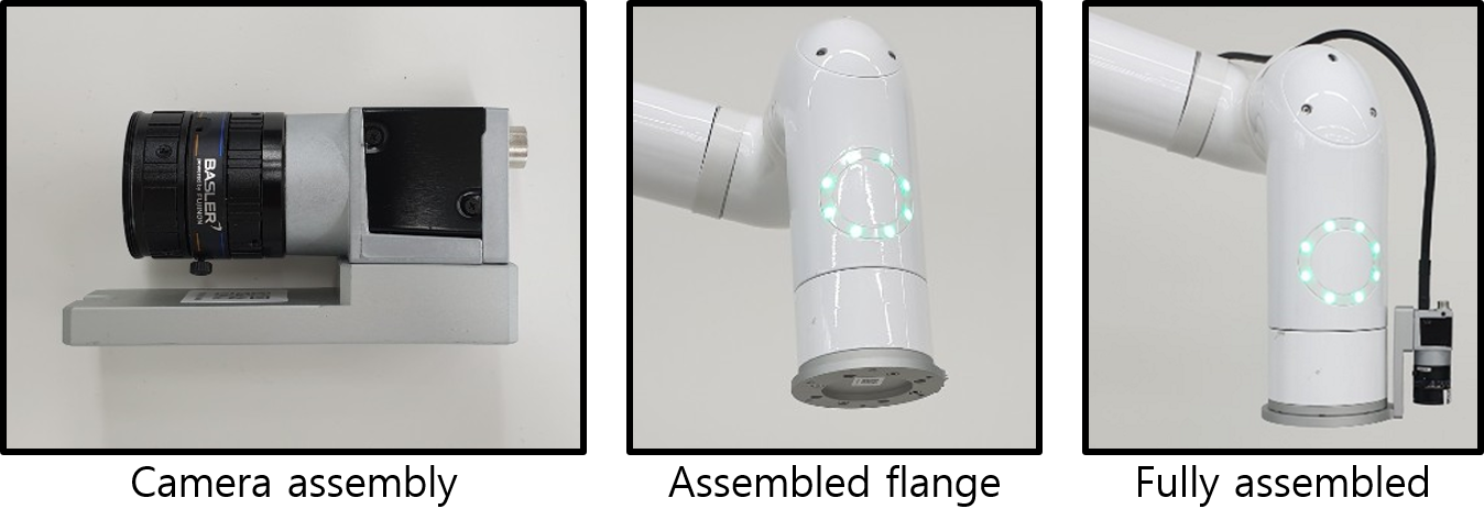
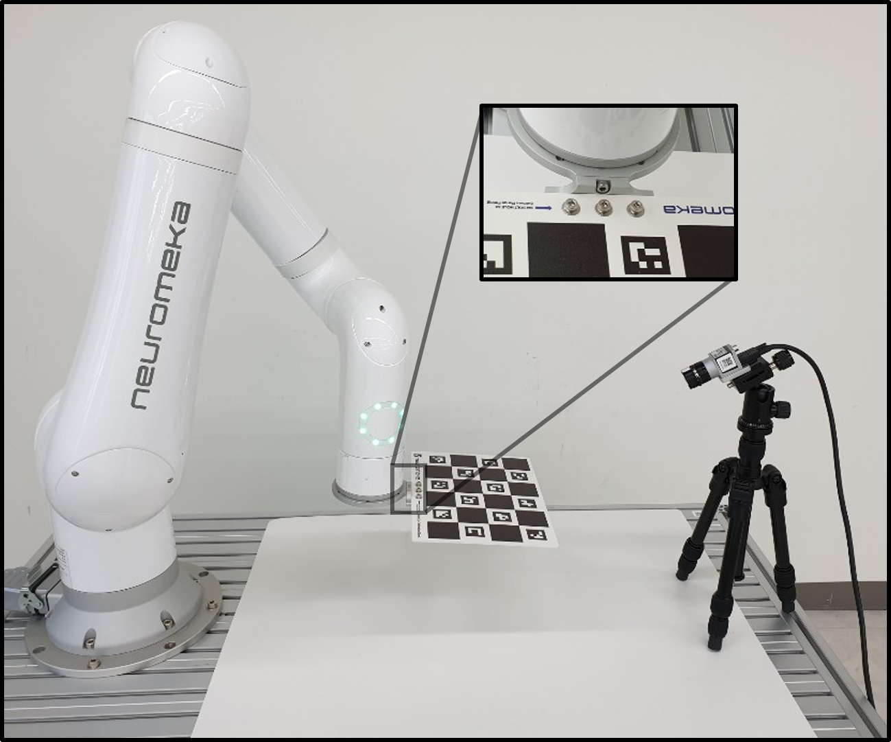
Installation
- Assemble the camera, lens and camera mount, using 3 M3×14 bolts.
- Attatch the flange to the end joint of Indy. Use 2 M4×6 pins and 4 M4×8 bolts.
- Attatch the camera mount to the flange, using 2 M3×8 pins and 1 M4×8 bolt.
- Connect the camera to the Eye-support USB port of IndyCB, using USB cable.
Accessing IndyEye
- After the camera assembly is fully assembled, connect the EtherNet port of IndyCB to local network and power on the IndyCB.
- To set up IndyEye, a separated web UI is used. To connect to the web UI, find the IP address of IndyEye and IndyCB using a 3rd party app, such as IP scanner. To distinguish IndyCB, look for an item with name "STEP-TP". To distinguish IndyEye, look for an item of which manufacturer is NVIDIA.
- When IndyEye and IndyCB is turned on, open a web browser and access to <IndyEye IP Address>:8088 to open IndyEye web UI.
IndyEye web UI
The left side of IndyEye web UI is camera panel. The images captured from the camera are displayed here. On the right side, there are 5 tabs: Robot, Calibration, Data, Detection and Pick.
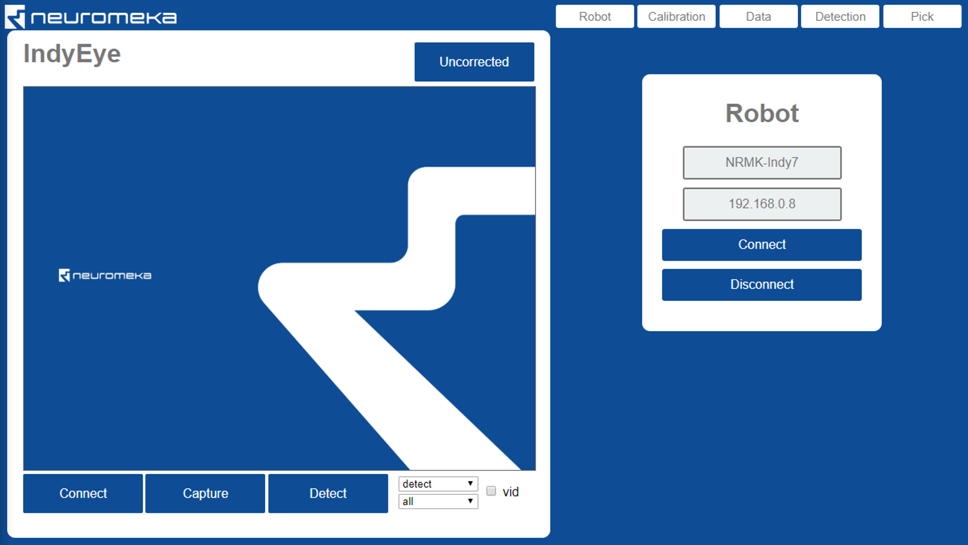
Connecting to camera
The camera will be automatically connected. Click connect button only when the connection is lost or you want to reset the exposure setting. Capture button will show the view. Check vid to get continuous video stream from the camera. Adjust lens focus to get clear sight.
Connecting to robot
- On the Robot tab, put the name and IP address of the robot.
- Click Connect.
Control robot
- When the robot is connected, you can see 7 edit boxes to control camera viewpoint.
| Value | Description | Unit |
|---|---|---|
| x | x-axis position of focal point | mm |
| y | y-axis position of focal point | mm |
| z | z-axis position of focal point | mm |
| u | 1st euler angle θz | degree |
| v | 2nd euler angle θx | degree |
| w | 3rd euler angle θz | degree |
| d | distance from focal point to camera | mm |
- The functions of buttons on the Robot tab are summarized below.
| Button | Description |
|---|---|
| Get | Get current camera viewpoint |
| Move | Move camera to the viewpoint that above edit boxes represent |
| Start DT | Start Direct Teaching Mode |
| Stop DT | Stop Direct Teaching Mode |
| Home | Move to Home position |
| Disconnect | Disconnect from the robot |
Calibration
Calibration of mounted camera
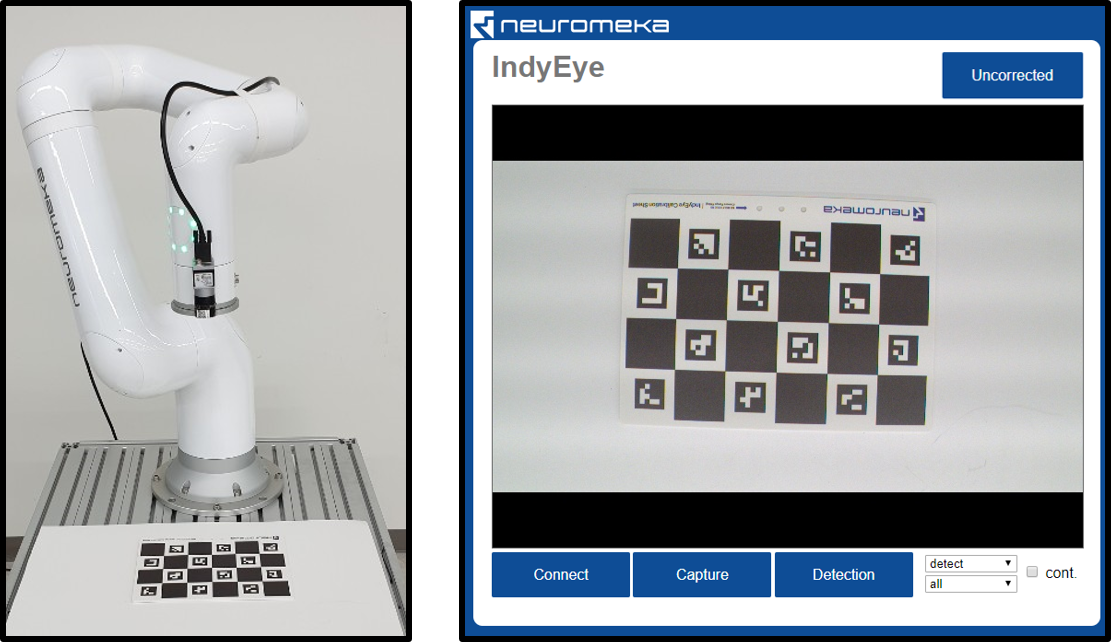
The camera parameters (focal length, center offset, distortion) and offset from end-effector should be calibrated by taking pictures of a Calibration sheet from various viewpoints.
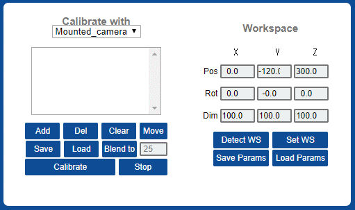
- Move the robot to its home position and open Calibration tab. Set Calibrate with "Mounted camera"
- Put calibration sheet in the working space. Make sure that the sheet is well-visible from the camera.
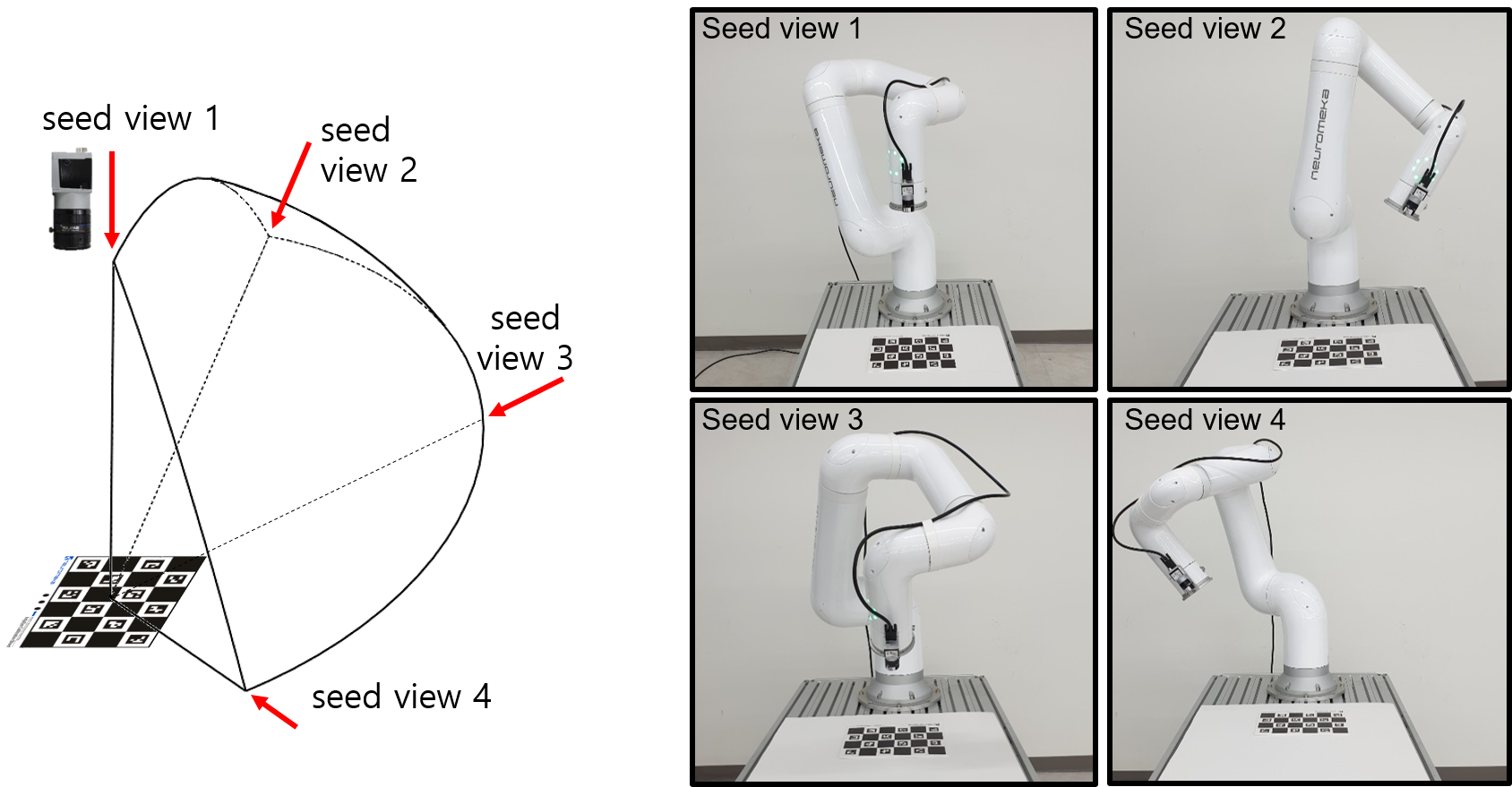
- Make seed view list to indicate the motion range for camera calibration process.
- Click Clear to empty the viewpoint list.
- Move the camera to seed viewpoints and add each viewpoint to the list by clicking Add button. You can use Direct Teaching or other method. (Warning: Try not to rotate last joint much.)
- The view list can be saved and loaded with save and load buttons.
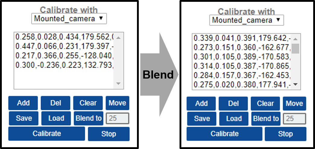
- Click Blend to to blend the viewpoints. It generates new viewpoints inside the area defined by seed viewpoints. The number of viewpoints can be edited with the box on the right side of the Blend to button.
- Click Calibrate to start the calibration. The robot moves automatically and takes pictures of the calibration sheet. After taking the pictures, the robot stops and IndyEye does computation to calibrate the camera. The computation takes under 1 minute. Wait until the UI flashes "Calibration is done".
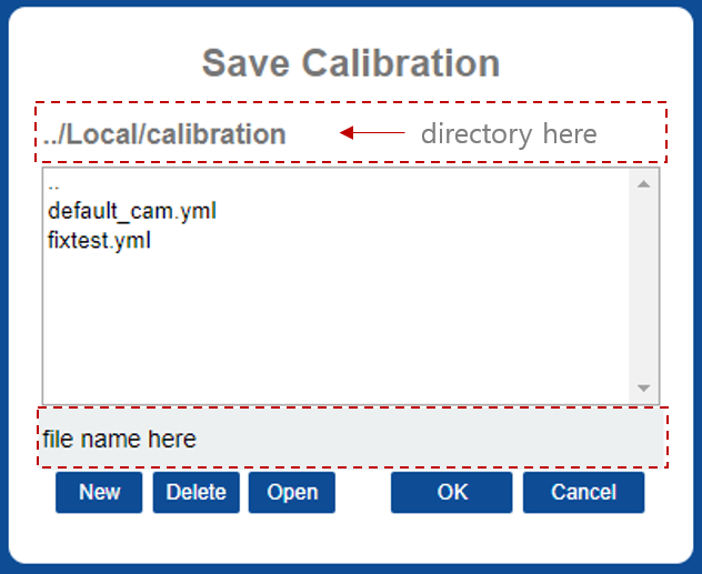
- Click Save Params to save calibration result. On the browser window, enter a file name and click OK. The default file name that is loaded on start-up is "default_cam.yml".
- After calibration, the camera distortion can be compensated. Click the button that says "Uncorrected" on the camera panel. The text on the button changes to "Undistorted" and the camera distortion is compensated.
Workspace
After calibration is done, you should set workspace by following sequence.
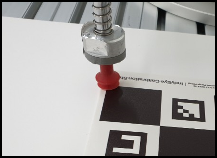
- Put the calibration sheet on the workspace and aim calibration sheet with camera.
- Warning: Set the x-axis of calibration sheet and x-axis of Indy end-effector in opposite direction. (Figure below) During picking task, the end-effector orientation will be chosen to be silmilar to this orientation.
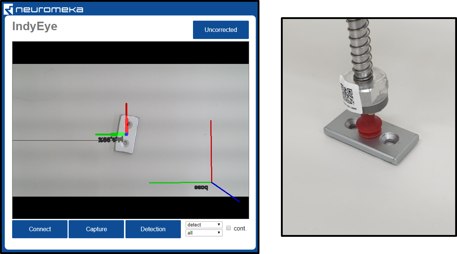
- Click Detect WS. The Workspace will be displayed on the camera image.
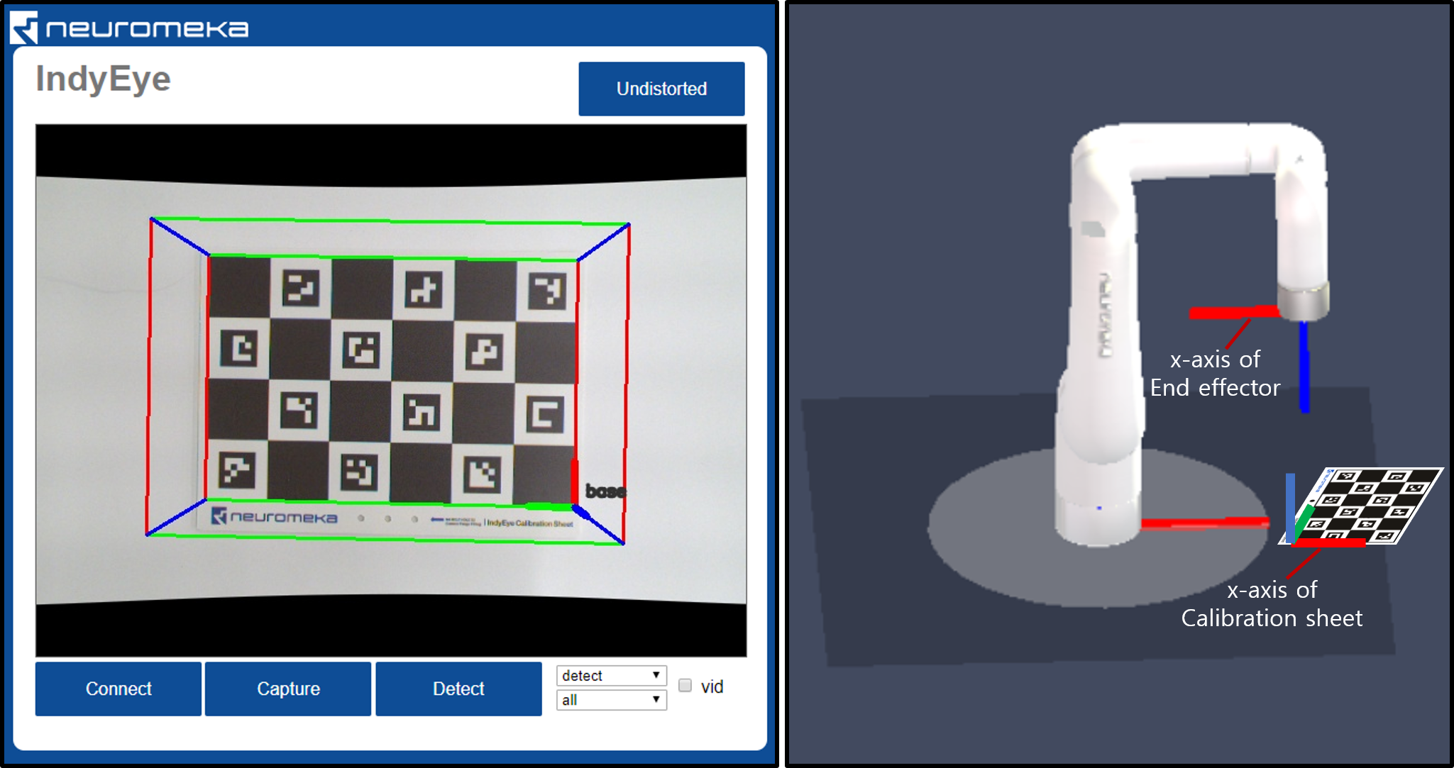
Detected workspace(left) and relation between Indy and workspace(right) - Edit workspace. There are 9 edit boxes which controls position, orientation and dimension of the workspace. Click Set WS to apply change.
- Click Save Params to save workspace.
Calibration of fixed camera
- Install camera on a fixed location.
- Set Calibrate with "Fixed Camera"
- Attatch the calibration sheet to the end joint of Indy using sheet mount, flange,8 M4×8 bolts, 2 M4×6 pins, 2 M3×8 pins and 3 M4 washers.
- Make seed view list and blend to many views. This time, the calibration sheet is moving, while the camera is fixed. Make sure calibration sheet is in the screen in every seed view.
- Click Calibrate to start the calibration. Wait until the UI flashes "Calibration is done".
- Click Save Params to save calibration result.
- Detach calibration sheet from Indy and go to Workspace section to set workspace.
Data collecting
Data collecting for object detection (pick and place)
To train deep-learning algorithm, you need to collect data. To collect data for object detection, you need CAD file(.stl). You can use any 3rd party 3D scanner or CAD software that can create stl file.
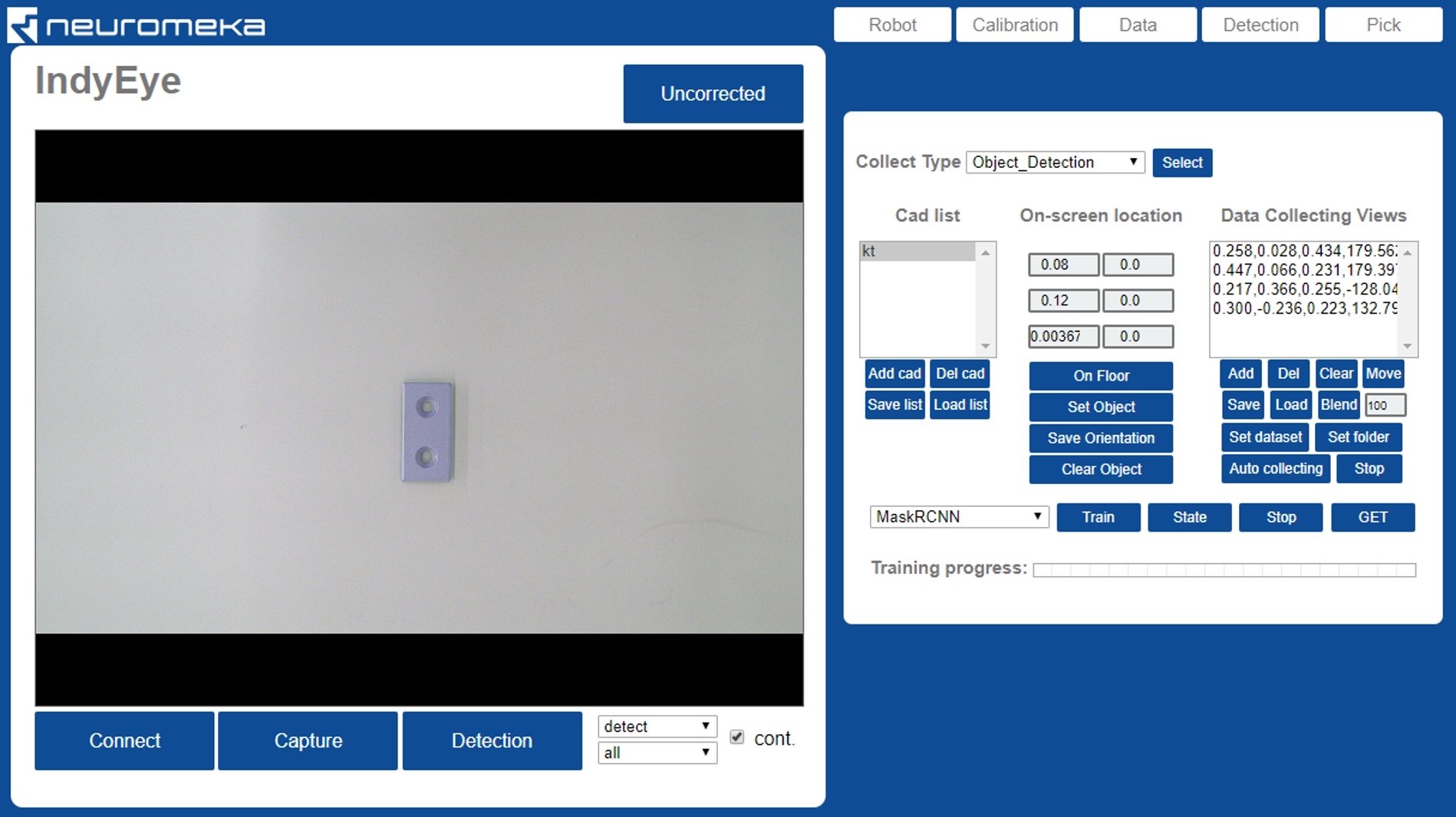
- Move the robot to its home position and open Data tab. Set collect type to "Object Detection"
- Make cad list.
- Click Clear to empty the list
- Put prepared CAD files to USB memory and plug it to the Eye-support USB port.
- Click Add cad to add cad file. Navigate to the USB memory, typically it is "/meida/nvidia/<USB_NAME>/".
- Select the CAD file you want to add and click OK.
- Repeat for all CAD files.
- Click Save list to save cad list. Enter or select a file name for the cad list and click OK.
- Select a cad model on the list and click On Floor. The selected cad model will be rendered on the center of the workspace.
- Put real object on the workspace. Make sure the object perfectly matches with the rendering, as in the figure above.
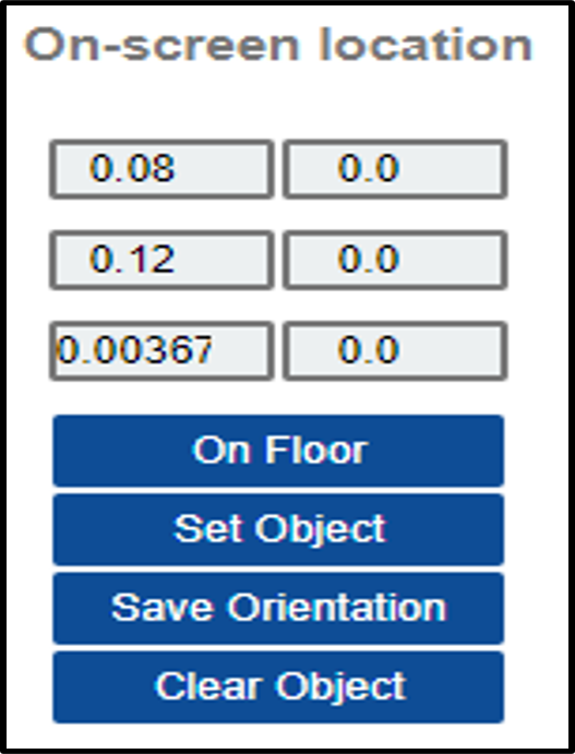
- On the On-screen location panel, the object rendering position can be adjusted.
- Edit left column values to adjust position.
- Edit right column values to adjust orientation.
- Set Object button applies the change change.
- Save Orientation button saves the changed orientation permanently.
- Clear Object removes the object from the screen.
- Create view list, in the same way as in the Calibration section. This time, the blending number should be 100 or more.
- Set dataset and folder.
- Click Set dataset to create or select the root folder for new dataset. Under the root folder, "train" and "val" folders are generated automatically.
- Click Set folder to designate a folder to save one sequence of data. Open the "train" folder, enter new folder name and click OK. One sequence of data will be stored this folder.
- Click Auto collecting.
- The robot will move and take pictures of workkpiece automatically. Wait until finished.
- To add data, change data folder by Clicking Set folder and giving new name, and repeat Auto collecting. It is desirable to collect images from all viewpoints that the object would be observed in actual task. In addition, It is optional but recommended to add folder(s) and collect additional dataset in "val" folder, for validation.
Data collecting for classification (inspection)
- Move the robot to its home position and open Data tab. Set collect type to "Inspection"
- Enter object (inspection point) name under Inspection Name.
- Create view list, in the same way as in the Calibration section.
- While creating seed viewpoint, aim the inspection point at a close distance and rotate around the inspection point.
- Blend to 100 or more viewpoints.
- Set dataset and folder.
- Click Set dataset to create or select the root folder for new dataset. Under the root folder, "train" and "val" folders are generated automatically.
- Click 'Set folder' to designate a folder to save one sequence of data. Open the "train" folder, enter new folder name and click OK. One sequence of data will be stored this folder.
- Click Auto collecting.
- The robot will move and take pictures of workpiece automatically. Wait until finished.
- To add data for other object (inspection point), enter other Inspection Name, change data folder by Clicking Set folder and giving new name, and repeat Auto collecting. It is desirable to collect images from all viewpoints that the object would be observed in actual task. In addition, It is optional but recommended to add folder(s) and collect additional dataset in "val" folder, for validation.
Deep learning
Training
- On the bottom side of Data tab, select network to train.
- MaskRCNN: Original MaskRCNN, just detect and segment objects on image.
- ResNet: Classifier for inspection.
- Click Train.
- In the file browser, select the dataset to train and click OK.
- The training progress is displayed on the bottom of the Data tab. It is also possible to check state of training server by clicking State. A message 'done' will be printed after training is over.
- If you want to stop training in the middle, click Stop.
Getting the trained network
- On the bottom side of Data tab, select network to download, and click GET.
- On the file browser titled 'Select Trained Config', open the dataset that you trained.
- Open 'Models' folder in the dataset directory.
- Select config file to download and click OK(By default, it is 'config.yml').
- On the file browser titled 'Download Config To', type or select a name for downloaded
configuration. Click 'OK'.
- The default configuration name is 'config.yml'.
- The configuration file, CAD file, and network weights are downloaded.
- For every overwritten files, backup file will be generated with a new name, <old_name_bak>.
- Wait until the model is downloaded and rotating icon disappears.
Detecting object
To set detection parameters, go to Detection tab.
- Click Load button on Options panel to load detection configuration. Select the configuration file that you created in the Getting the trained network section. It takes time to initialize deep learning algorithm. Wait until loading is done and the rotating icon disappears.
- Click Detect to try detection. In the case of MaskRCNN, the first detection takes time for initialization. To modify detection algorithm, check Detect tab section below.
- MaskRCNN can be accelerated 3 times faster with SoyNet. Change Deep learning option to MaskRCNNSoyNet and click Save. Type a new name for new configuration and click OK.
- It takes time to convert the model. Wait until conversion is done and the rotating icon disappears.
- Now the SoyNet accelerator is applied. Click Detect to test detection.
Detection tab
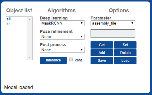
- Object list : List of object. Same as cad list in the Data tab.
- Algorithms : List of available algorithms.
- Deep learning : Deel learning algorithms
- MaskRCNN: MaskRCNN object detection.
- MaskRCNNSoyNet: MaskRCNN object detection, accelerated with SoyNet. SoyNet license is needed to use this module.
- ResNet: ResNet Classifier for inspection.
- Pose refinement : Optional algorithms for object pose refinement.
- PCA: Align x axis with main principal axis of mask.
- SilhouetteSimple: Find accurate pose by matching silhouette of the object.
- Workspace: Set object location same as workspace origin. Test purpose.
- Post process : Optional post process.
- Crosscheck: Cross-check among classes. Find best silhouette-matching class.
- Detect button: Detect object which is selected on the Object list.
- Deep learning : Deel learning algorithms
- Options : view and edit detection parameters.
- Get: Get selected parameter value.
- Set: Set selected parameter with value entered above.
- Add: Add a new parameter, with name entered above.
- Delete: Delete selected parameter
- Save: Save configuration.
- Load: Load configuration.
- Example: Limit detection space to the workspace
- Enter 'check_workspace', click Add
- Enter 1, click Set
- Click Save to save the configuration.
- Only objects inside the workspace will be detected afterward.
| option | Used algorithm | value | description |
|---|---|---|---|
| 'mrcnn_conf_cut' | MaskRCNN | 0~1 | Detection cutline of MaskRCNN |
| 'rot_range' | SilhouetteSimple | 0~360 | Range of angle for rotating inspection |
| 'track_iter' | SilhouetteSimple | int | Number of angular resolution of rotating inspection (Ex: 8 means 'rot_range' will be divided into 8) |
| 'track_scales' | SilhouetteSimple | int | Number of iterations (Rotating inspection is done repetitively, narrowing the range ) |
| 'iou_cut' | SilhouetteSimple,Crosscheck | 0~1 | Lower bound of the silhouette matching rate |
| 'class_group' | Crosscheck | int array | An int array of the number of objects. Cross-examination is performed only among objects set to the same number. (Ex: [0, 0, 1, 1] → First and second, third and fourth are compared to each other) |
Pick options
Teaching how to pick object
First, the tool center position (TCP) should be taught.
- Put Calibration sheet on the workspace.
- In Calibration tab, click Detect WS. You will see workspace with base axes.
- Move to Pick tab.
- Move robot tool to the origin point of the workspace.
- In Tools panel, click Teach to teach the TCP.
- Multiple tools can be registered. When detecting object, algorithm selects one best tool in terms of orientation.
- In the number list, 1st and 2nd are tool indexes. 3rd represents symmetry. i.e., 2 means the tool is symmetric in 180°rees;, while 4 means the tool is symmetric in 90°rees;. After editing the numbers, click Edit to apply changes.
- 4~9th numbers are 6 DoF coordinate of TCP offset. (x,y,z,θx, θy, θz)
-
Click Save to save TCP list.
Next, for each object, available grip point should be taught.
- Put target object on workspace.
- In Camera panel, select the object in the list and click Detect. The detection result will be displayed.
- On Grips panel, select target object and click Select.
- On Tools panel, select TCP to use for teaching grip.
- Move robot tool to desirable pick point.
- In Grips panel, click Teach to teach pick point.
- Multiple pick points can be registered. When detecting object, algorithm selects one best pick point in terms of orientation.
- 1~4th numbers in pick points are for selecting tools. It is automatically entered when it is taught.
- 5~10th numbers are 6DoF coordinate of pick point. (x,y,z,θx, θy, θz)
-
Click Save to save current grip points.
Teaching grip position: Detect object and place tool on a desirable grip point.
After all teaching process finished, you can test pick.
-
Test-draw tool position.
- Select a TCP on the list in Tools panel.
- Click draw on Tools panel.
- The tool axis is drawn on the screen. Normally, the tool is not fully visible. From camera.
-
Test-draw grip position.
- Put test object on workspace.
- Select the object on Camera panel and click Detect. The detected object is displayed on the screen.
- Select the object on Grips panel, Click Select and select one grip point from the list.
- Click draw on Grips panel.
- The grip point for the object is drawn on the screen.
-
Test-Pick
- Put test object on workspace.
- Select the object on Camera panel and click Detect. The detected object is displayed on the screen.
- Click Pick Test
- Robot moves the tool to the detected grip point of the object.
TCP/IP communication
Communication protocol Once the detection setting is done in the Web UI, detection can be requested and results can be received using TCP/IP socket. IndyEye use json string for TCP/IP communication. The command format is as follows.
| key | value | description |
|---|---|---|
| 'command' | 0 | run deep learning algorithm |
| 1 | pose refinement and post processing | |
| 2 | reset detection algorithm | |
| 3 | request list of detectable object names | |
| 'class_tar' | int | index of target object class. To detect all, give 0 |
| 'pose_cmd' | float x 6 array | Current task position of robot. (optional, only when IndyEye is in 'no robot' mode) |
As a response, IndyEye returns json string in following format.
| key | value | description |
|---|---|---|
| 'STATE' | int | Error state. 0 means detection is successful. |
| 'class_detect' | int | Index of detected class, starting from 1. |
| 'tool_idx' | int | Index of selected tool from indyeye. |
| 'Tbe' | float x 6 array | 6D task position to pick object. |
| 'Tbt' | float x 6 array | 6D Tool Center Position to pick object. |
| 'Tbo' | float x 6 array | 6D Position of detected object. |
| 'class_list' | string array | list of detectable object names. (returned only when command was 3) |
C++ client
IndyEyeClient is a C++ communication client which is provided with IndyEye. It is included in NRMK Framework and contents are as follows.
| file/folder | content |
|---|---|
| IndyEyeClient.h | header file for IndyEyeClient. |
| IndyEyeClient.cpp | source file for IndyEyeClient. |
| jsoncpp.cpp | source file for JsonCpp library, which is used to interpret json. |
| json/ | directory containing headers for JsonCpp library |
IndyEyeClient provides convenient wrapper functions for TCP/IP communication with IndyEye. All functions of IndyEyeClient are listed below.
| function | argument | description |
|---|---|---|
| SetIP | char* ipaddress | Set Ip address of IndyEye |
| GetClassList | - | Get detectable object list |
| Detect | int cls, double *pose | Detect object and refine detection. cls: target class index, 0 means all class. pose: current task pose of robot, double × 6 array |
After calling GetClassList and Detect, response from IndyEye is saved in the member variables of IndyEyeClient, as follows.
| member variable | type | description |
|---|---|---|
| class_detect | int | class of detected object |
| Tbe | float x 6 array | 6D task position to pick object. |
| Tbt | float x 6 array | 6D Tool Center Position to pick object. |
| Tbo | float x 6 array | 6D Position of detected object. |
| class_list | vector |
list of detectable object names |
Example program with object detection
***Pick and place in Python ***
Following is an Python example of pick and place program, which picks object and puts it 5 cm away from the pick position. (To run this code, IndyDCPClient is needed. It is included in NRMK Framework, inside indydcp_client.py. Please refer to IndyInterfaces section.)
1 2 3 4 5 6 7 8 9 10 11 12 13 14 15 16 17 18 19 20 21 22 23 24 25 26 27 28 29 30 31 32 33 34 35 36 37 38 39 40 41 42 43 44 45 46 47 48 49 50 51 52 53 54 55 56 57 58 59 60 61 62 63 64 65 66 67 68 69 70 71 72 73 74 75 76 77 78 79 80 81 82 83 84 85 86 87 88 89 90 91 92 93 94 95 96 97 98 99 100 101 102 103 104 105 106 107 108 109 110 111 112 | |
Object detection in C++
Following is an example of detecting object in C++. It includes how to get the list of object names.
1 2 3 4 5 6 7 8 9 10 11 12 13 14 15 16 17 18 19 20 21 22 23 24 25 26 27 | |
Advanced app management
App execution
- Type one of the following commands to execute the app server.You can execute it in terminal or execute as service(second command). (By default, the app is executed in the second method)
1 2 | |
or
1 | |
Background service management
- To check status of the app when it is running on background service, type the command below.
1 | |
- To kill the app when it is running on background service, type the command below.
1 | |
